
High-voltage discharging rod

A high-voltage discharge and discharge rod technology, applied in corona discharge devices, circuits, electrical components, etc., can solve problems such as safety hazards, insufficient voltage resistance of insulating rods, wire wear, etc., to achieve convenient installation and transportation, improve safety and reliability, simple structure

Active Publication Date: 2013-12-25
GLORYMV ELECTRONICS
View PDF5 Cites 0 Cited by
  • Summary
  • Abstract
  • Description
  • Claims
  • Application Information

AI Technical Summary

Problems solved by technology

[0005] Since the length of the insulating rod is fixed, when the rod is too long, its transportation is inconvenient
When the rod body is too short, it is not convenient for long-distance use; when it discharges the high-voltage energy storage element, it may also cause a safety hazard due to the insufficient withstand voltage of the insulating rod
Moreover, the grounding wire is generally exposed outside the insulating rod body, which is easy to cause the wear of the wire and reduce its reliability.

Method used


Image

  • High-voltage discharging rod
  • High-voltage discharging rod
  • High-voltage discharging rod

Examples


Embodiment Construction

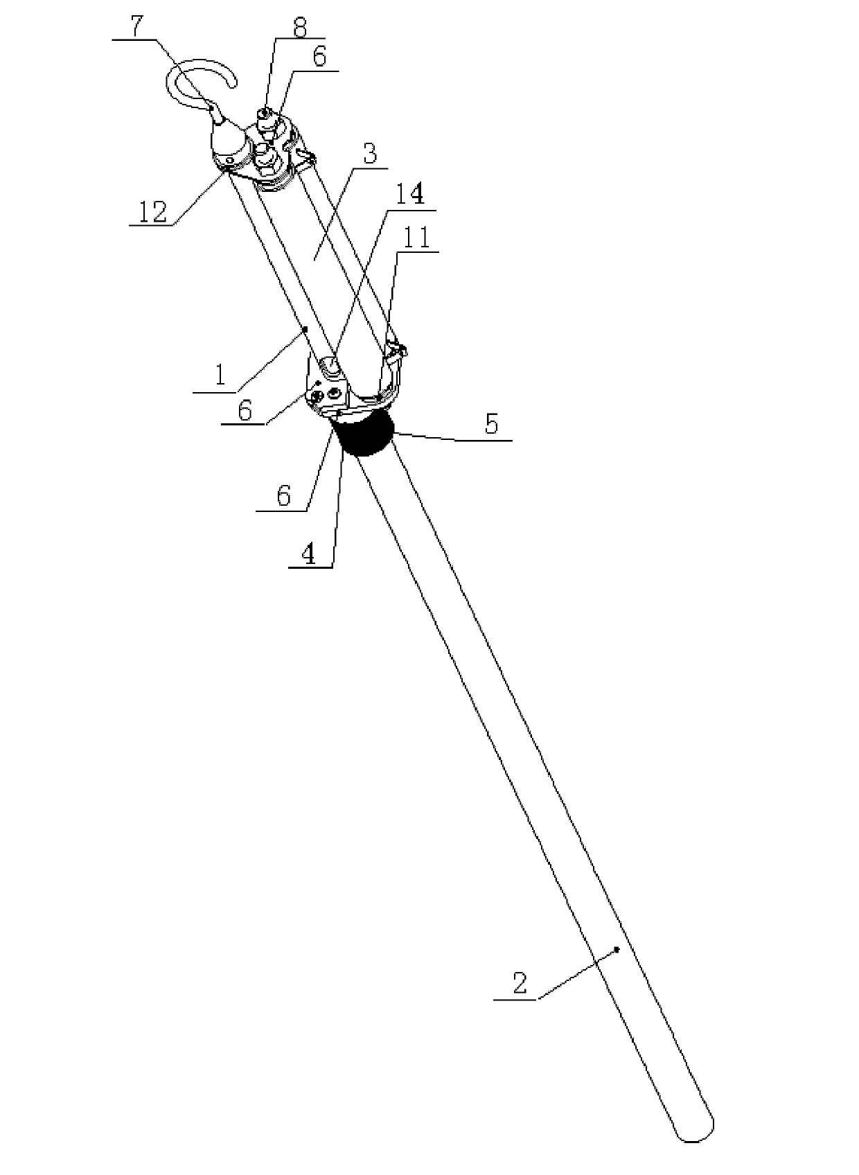
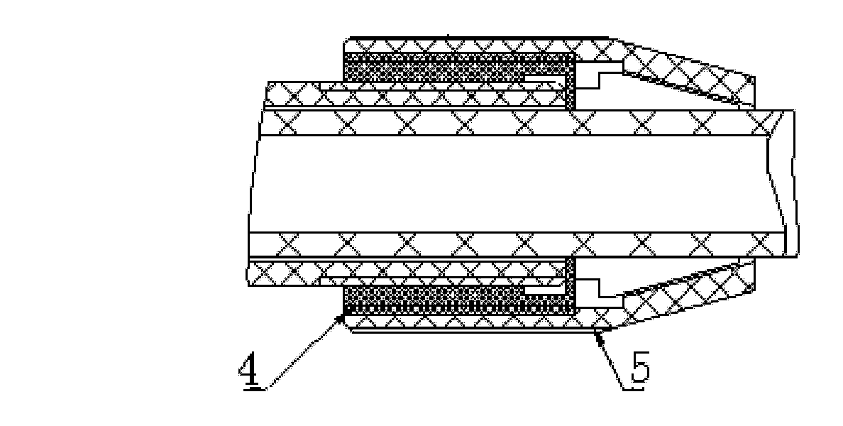
[0022] Such as figure 1 As shown, the present invention is that the inner rod 1 of the discharge rod and the outer rod 2 of the discharge rod are mutually fitted, and the inner rod 1 of the discharge rod and the outer rod 2 of the discharge rod are both hollow structures; the inner rod 1 of the discharge rod is connected to the discharge resistor 3 through a support plate 6 , and its top is connected with a discharge hook 7; one end of the discharge resistor 3 is connected to the discharge hook 7, and the other end is connected to the ground wire and passes through the inner cavity of the inner rod 1 of the discharge rod and the outer rod 2 of the discharge rod, thereby passing through the discharge rod The mutual cooperation between the inner rod 1 and the outer rod 2 of the discharge rod adjusts the length of the entire discharge rod, and leads the ground wire out of its inner cavity to protect the ground wire. The discharge resistor 3 is a power type wirewound resistor.

...


PUM


Abstract

The invention discloses a high-voltage discharging rod. The high-voltage discharging rod is characterized in that: according to the discharging rod, a discharging-rod inner rod and a discharging-rod outer rod are mutually sleeved on each other, and the discharging-rod inner rod and the discharging-rod outer rod are hollow structures; the discharging-rod inner rod is connected to a discharging resistor through a support plate and a top is connected with a discharging crotch; one end of the discharging resistor is connected to the discharging crotch, and the other end is connected with a ground wire and passes through the discharging-rod inner rod and a discharging-rod outer rod cavity. The above structure has the following advantages that: 1. adjustment of a discharging rod length can be realized; 2. a grounding lead of the resistor passes through a long waist hole of the discharging rod and the cavity of the discharging rod so as to protect the lead and increase safety and reliability; 3. the high-voltage discharging rod structure is simple, safe and reliable, installation and transportation are convenient.

Description

[0001] Involved areas [0002] The invention relates to debugging and maintenance of a high-voltage pulse modulator, in particular to a high-voltage discharge rod. Background technique [0003] At present, the high-voltage discharge rod has become an indispensable tool for debugging and overhauling the high-voltage pulse modulator. The working principle of the high-voltage discharge rod is to discharge through the discharge conductor first, and then discharge through the grounding lead for a second time, so that the energy storage element of the device is completely discharged. [0004] The main structure of the current high-voltage discharge rod is to install a discharge hook and a grounded solid conductor on an insulating rod. The high-voltage discharge rod is generally placed in the high-voltage pulse modulator to discharge it. [0005] Since the length of the rod body of the insulating rod is fixed, when the rod body is too long, it is inconvenient to transport. When th...

Claims


Application Information

Patent Timeline
Patent Type & Authority Patents(China)
IPC IPC(8): H01R11/12H01R43/00H01T19/00
Inventor 聂玉春宫龙刘林王年峰
Owner GLORYMV ELECTRONICS
Learn More