
Method of manufacturing carburized parts

By setting the machined surface roughness of the non-carburized part to Rz50 or above in the manufacture of carburized parts, the edge effect is used to suppress carburization, which solves the problems of high cost and complicated processing in the existing technology, and achieves simplified processing and Improve the effect of welding performance.

Inactive Publication Date: 2012-06-27
TOYOTA JIDOSHA KK
View PDF10 Cites 7 Cited by
  • Summary
  • Abstract
  • Description
  • Claims
  • Application Information

AI Technical Summary

Problems solved by technology

[0003] If the entire part is carburized, although the surface hardness of the part is improved by carburizing, there are problems such as difficulty in processing and easy cracking or cracking during welding.

Method used


Image

  • Method of manufacturing carburized parts
  • Method of manufacturing carburized parts
  • Method of manufacturing carburized parts

Examples


Embodiment Construction

[0044] First, a first embodiment of the present invention will be described.

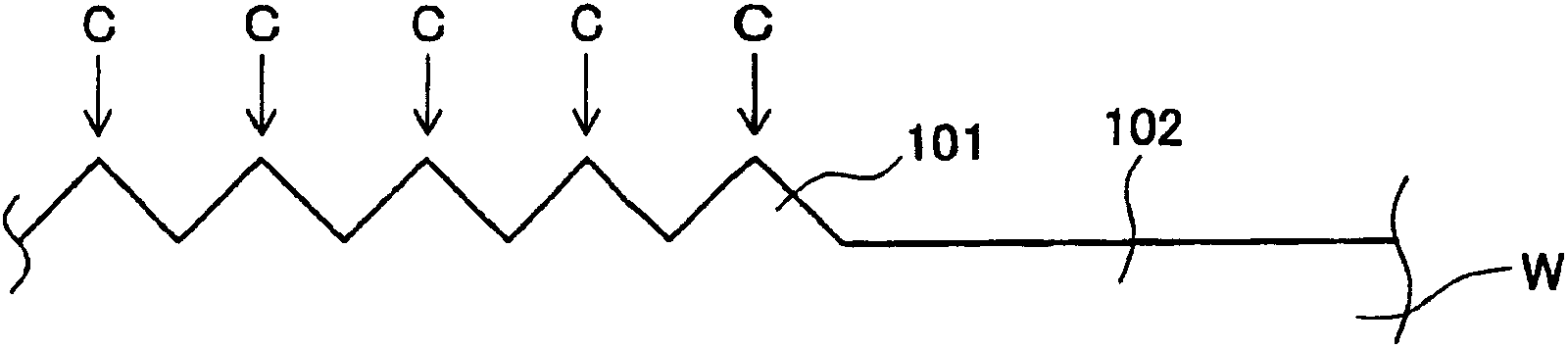
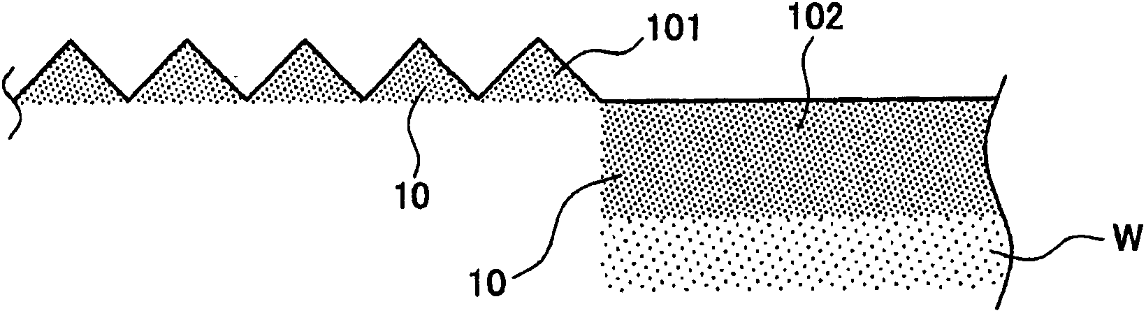
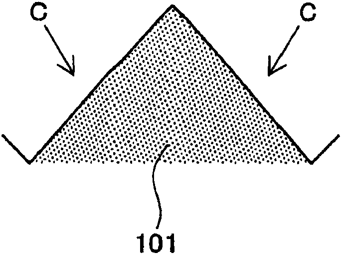
[0045] figure 1 A cross-sectional view showing a state before carburizing of the first embodiment is shown. figure 2 A cross-sectional view showing a state after carburizing is shown. image 3 show figure 2 enlarged section view of . Figure 4 A perspective view of a workpiece W is shown.

[0046] Assuming that the workpiece W is steel for mechanical parts, Figure 4The workpiece W shown is a shaft with a simple shape. By placing such a workpiece W in a vacuum furnace and performing carburizing treatment, the carbon content on the surface of the workpiece W can be increased to improve wear resistance. The workpiece W is as Figure 4 A cylindrical shaft is shown having a first machined surface 101 and a second machined surface 102 . In addition, although the shape of the workpiece W is simplified for convenience of description, other complicated shapes are also possible.

[0047] figure 1...


PUM


Abstract

To provide a method of manufacturing a carburized part contributable to cost reduction, a portion intended for a non-carburizing portion is treated to a surface roughness corresponding to Rz 50 like a first work surface and a portion intended for a carburizing portion is treated to a surface roughness corresponding to Rz 1.5 like a second work surface.

Description

technical field [0001] The present invention relates to a technology for suppressing carburization by changing surface roughness according to parts of parts when manufacturing carburized parts. Background technique [0002] Steel parts constituting machinery include many friction parts, and therefore are required to have wear resistance in many cases. A technique of improving wear resistance by carburizing the surface of a part formed of steel material is also applied to parts for automobiles. Carburized parts are actually used everywhere in the car. [0003] If carburizing the entire part, although the surface hardness of the part is improved by carburizing, there are problems such as difficulty in processing, and cracks or cracks easily occurring during welding. Therefore, there is a need to locally perform carburizing treatment only on necessary parts. Therefore, various studies have been made in order to obtain a part in which no carburizing treatment is performed on ...

Claims


Application Information

Patent Timeline
Patent Type & Authority Applications(China)
IPC IPC(8): C23C8/02C21D1/06C21D9/28C21D9/32C23C8/20F16H55/06
CPCC21D2221/00C21D1/06C23C8/04C23C8/20C23C8/02C21D1/74C21D1/613
Inventor 坂上秀幸稻垣功二三林雅彦清水拓也
Owner TOYOTA JIDOSHA KK
Learn More