Longitudinal adjusting and auxiliary welding line alignment device for welding gun of special circumferential welding machine for automotive transmission shaft

A technology for aligning devices and transmission shafts, applied in auxiliary devices, auxiliary welding equipment, welding/cutting auxiliary equipment, etc.

Inactive Publication Date: 2012-07-04
SHANGHAI UNIV
View PDF8 Cites 5 Cited by
  • Summary
  • Abstract
  • Description
  • Claims
  • Application Information

AI Technical Summary

Problems solved by technology

However, because the welding area is far away from the operating area, the adjustment of the welding torch cannot achieve the desired effect

Method used


Image

  • Longitudinal adjusting and auxiliary welding line alignment device for welding gun of special circumferential welding machine for automotive transmission shaft
  • Longitudinal adjusting and auxiliary welding line alignment device for welding gun of special circumferential welding machine for automotive transmission shaft
  • Longitudinal adjusting and auxiliary welding line alignment device for welding gun of special circumferential welding machine for automotive transmission shaft

Examples


Embodiment 1

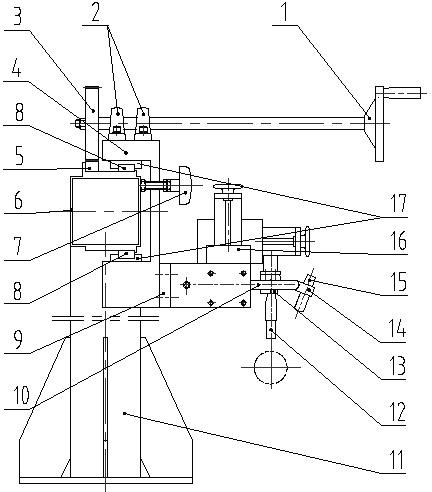
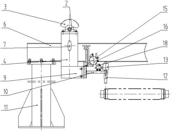
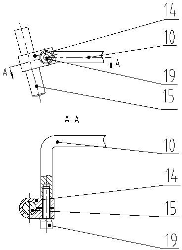
[0012] see figure 1 , figure 2 , image 3 : The longitudinal adjustment of the welding torch and the auxiliary welding seam alignment device of the special machine for girth welding of automobile transmission shafts. On the upper and lower planes of the two slides (17) respectively slide on the two linear guides (8), and the longitudinal slide (4) is fixedly installed on the slides (17); the welding torch adjustment assembly (16) is connected through the adjustment assembly (9) Installed on the front end of the longitudinal slide table (4), the bearing assembly (2) is fixedly installed above the longitudinal slide table (4), the handwheel shaft (1) is installed in the bearing assembly (2), and a gear (3) is installed at its rear end. ); a rack (5) is fixedly installed on the upper plane of the longitudinal beam (6), when the handwheel shaft (1) rotates, the gear (3) meshes with the rack (5), driving the longitudinal slide (4) along the longitudinal direction The beam (5) ...

Embodiment 2

[0014] This embodiment is basically the same as the first embodiment, and the special features are:

[0015] The longitudinal beam (6) is fixedly mounted on the structure of the foot (11); the left end of the longitudinal beam (6) is fixedly connected to the top panel of the foot (11) through bolts and nuts to form a cantilever structure.

[0016] The welding torch adjustment assembly (16) is a vertical position adjustment mechanism composed of a vertical handwheel screw matching nut and a longitudinal position adjustment mechanism composed of a longitudinally moving handwheel screw matching.

[0017] The working principle of this embodiment is as follows:

[0018] When installing and debugging the equipment, keep the longitudinal position of the laser transmitter and the welding torch on the same plane.

[0019] When it is necessary to adjust the longitudinal position of the welding torch, first loosen the locking bolt that locks the longitudinal moving slide, and manually r...


PUM


Abstract

The invention relates to a longitudinal adjusting and auxiliary welding line alignment device for a welding gun of a special circumferential welding machine for an automotive transmission shaft. A welding area is far away from an operating area, and the longitudinal position of the welding gun needs to be adjusted in a long distance, so that a gear rack mechanism is used for wide-range longitudinal adjustment, the transverse length of a hand wheel shaft is increased, and operation is facilitated for operators. Besides, laser spots are used for assisting in aligning positions of welding lines. When the welding gun is longitudinally adjusted, a laser transmitter synchronously moves along with the welding gun, and the working position of the welding gun is positioned by red laser spots emitted by the laser transmitter, so that the adjusting position of the welding gun is conveniently determined by the operators. The device can be applied to longitudinal adjustment and welding line alignment for the welding gun of the special welding machine, and the welding gun of the special welding machine is adjusted more simply and conveniently, so that production efficiency can be improved, and labor intensity is reduced.

Description

technical field [0001] The invention relates to a welding torch longitudinal adjustment and auxiliary welding seam alignment device used in a special machine for circular welding of an automobile drive shaft, which is characterized in that a rack and pinion mechanism is used to realize a large-scale longitudinal adjustment, and the transverse length of the adjustment handwheel shaft is increased , It is convenient for the operator to operate. At the same time, the laser spot is used to assist the alignment of the welding seam position, which is convenient for the operator to determine the adjustment position of the welding torch. It can be applied to the longitudinal adjustment of the welding torch and the alignment of the welding seam in the welding machine. Background technique [0002] The special welding machine for automobile transmission shaft ring is a fully automatic welding equipment with two stations of loading and unloading and welding. To achieve the ideal weldin...

Claims


Application Information

Patent Timeline
Patent Type & Authority Applications(China)
IPC IPC(8): B23K37/00B23K37/02
Inventor 华晓青徐智武吴惠兴王力隋立军
Owner SHANGHAI UNIV
Why Eureka
Try Eureka