Special fixture for radial porous parts

A technology for special fixtures and parts, which is applied in the field of special fixtures for radially porous parts, which can solve problems such as low efficiency, unstable part size tolerances, and low efficacy, so as to avoid the time spent on clamping and multiple times of pulling large holes. The effect of stable product quality and improved processing efficiency

Inactive Publication Date: 2012-07-04
JIANGSU WANGONG TECH GRP CO LTD
View PDF5 Cites 3 Cited by
  • Summary
  • Abstract
  • Description
  • Claims
  • Application Information

AI Technical Summary

Problems solved by technology

The main problem of this method is one: many clamping times, low efficiency and easy to cause cumulative errors; two: the position between holes has a lot to do with the operator
These problems lead to low efficiency and unstable part dimensional tolerances

Method used


Image

  • Special fixture for radial porous parts
  • Special fixture for radial porous parts
  • Special fixture for radial porous parts

Examples


Embodiment Construction

[0023] The present invention will be described in detail below with reference to the accompanying drawings and in combination with embodiments.

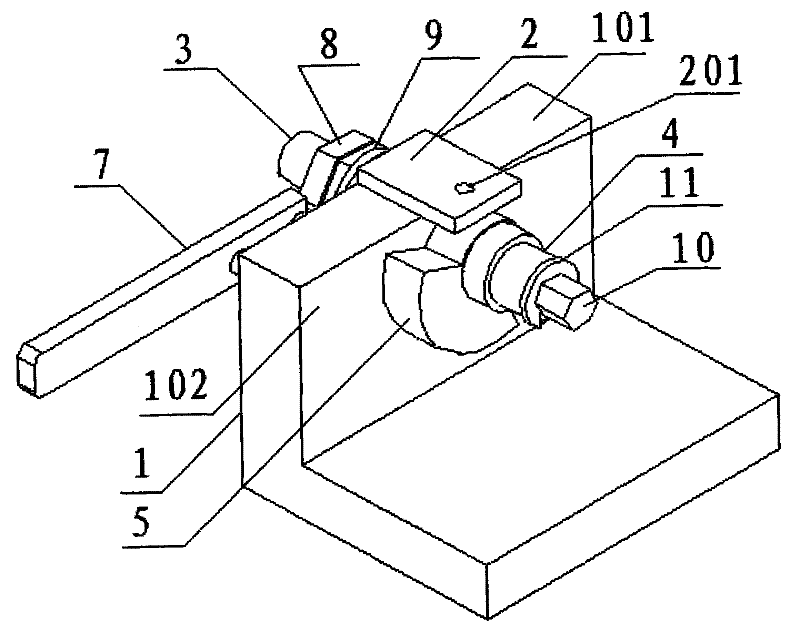
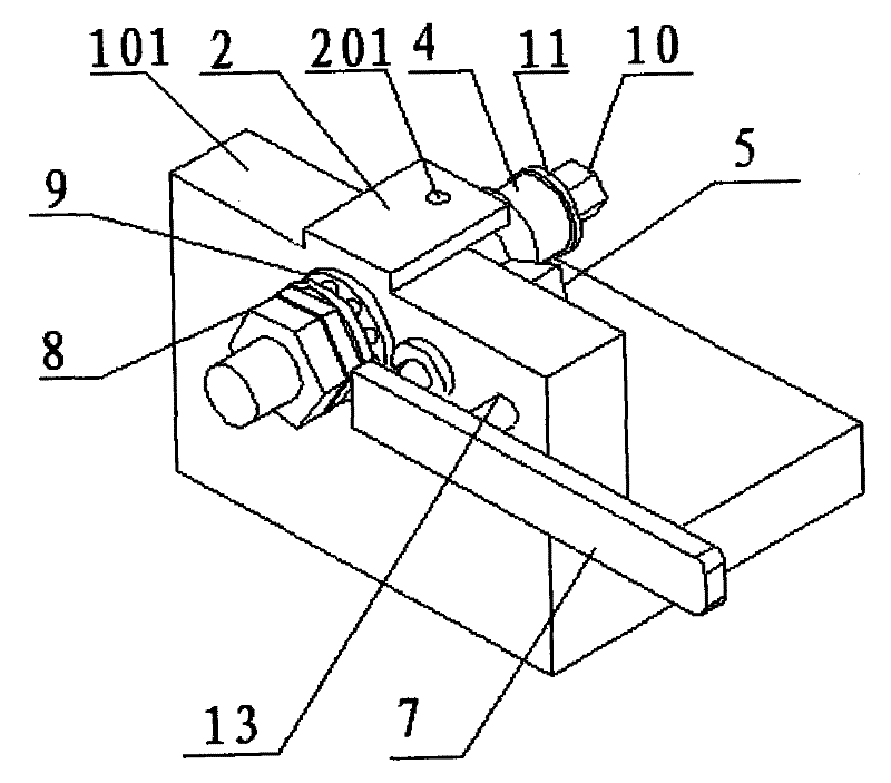
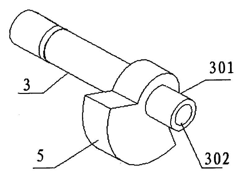
[0024] see figure 1 , figure 2 , image 3 , Figure 4 , Figure 5 As shown, a special fixture for radially porous parts includes a base 1, the base 1 includes a first plane 101 and a second plane 102 perpendicular to each other, and the first plane 101 is installed with Drilling template 2, the drilling template 2 is provided with a hole position 201, and the second plane 102 is provided with a screw hole and a tie rod hole; a screw 3 is rotatably arranged in the screw hole, and the screw 3 One end below the drilling template 2 is a positioning shaft 301 for installing the part 4 to be processed, and a positioning block 5 is also fixed on the screw 3, and the positioning block 5 is arranged on the positioning shaft 301 and the base 1 Between, a plurality of positioning pits 501 are arranged on the panel of the positioning block...


PUM


Abstract

The invention relates to a special fixture for radial porous parts, and the special fixture comprises a base, wherein the base comprises a first plane and a second plane which are vertical to each other, a drilling template is arranged on the first plane, a hole site is formed on the drilling template, and a screw hole and a draw bar hole are formed on the second plane, a screw is rotatably arranged in the screw hole, one end, positioned below the drilling template, of the screw is provided with a locating shaft for installing a part to be processed, the screw is also fixedly provided with a locating block, the locating block is arranged between the locating shaft and the base, a panel, opposite to the base, of the locating block is provided with a plurality of locating pits, a draw bar is rotatably arranged in the draw bar hole, one end of the draw bar is connected to a draw bar handle, the other end of the draw bar is provided with a draw bar contact head which can retract under external action and extend in a free state, the draw bar contact head is arranged at one side, which is provided with the locating block, of the base, and the draw bar contact head is positioned in the locating pits when in the free state. After the fixture is used, the processing efficiency is greatly improved and the product quality is stable.

Description

technical field [0001] The invention relates to a fixture for processing parts, in particular to a special fixture for radial porous parts. Background technique [0002] In the previous processing process of radial porous parts, one hole was processed first, and then the rest of the holes were positioned with the first processed hole to ensure the positional degree between the holes in turn. The main problem of this method is one: many clamping times, low efficiency and easy to cause cumulative errors on the other hand; two: the position between holes has a lot to do with the operator. These problems lead to inefficiency and unstable part dimensional tolerances. Contents of the invention [0003] The present invention aims at the above-mentioned deficiencies in the prior art. The purpose of the present invention is to provide a special fixture for radially porous parts, which can complete porous processing by one clamping, avoiding multiple clamping and multiple The time...

Claims


Application Information

Patent Timeline
Patent Type & Authority Applications(China)
IPC IPC(8): B23Q3/02
Inventor 潘本利徐福明
Owner JIANGSU WANGONG TECH GRP CO LTD
Why Eureka
Try Eureka