
Device for laying a cover

A cover and supply station technology, applied in book binding, transportation, packaging, printing, etc., to achieve the effect of minimizing the time for assembly and adjustment

Active Publication Date: 2012-07-04
MULLER MARTINI HLDG
View PDF13 Cites 4 Cited by
  • Summary
  • Abstract
  • Description
  • Claims
  • Application Information

AI Technical Summary

Problems solved by technology

The problem is the sizing of the needle element for a large number of cover materials

Method used


Image

  • Device for laying a cover
  • Device for laying a cover
  • Device for laying a cover

Examples


Embodiment Construction

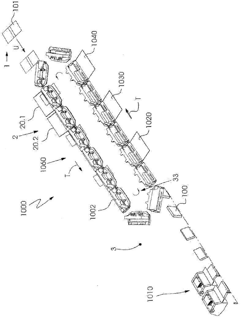
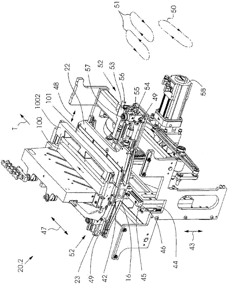
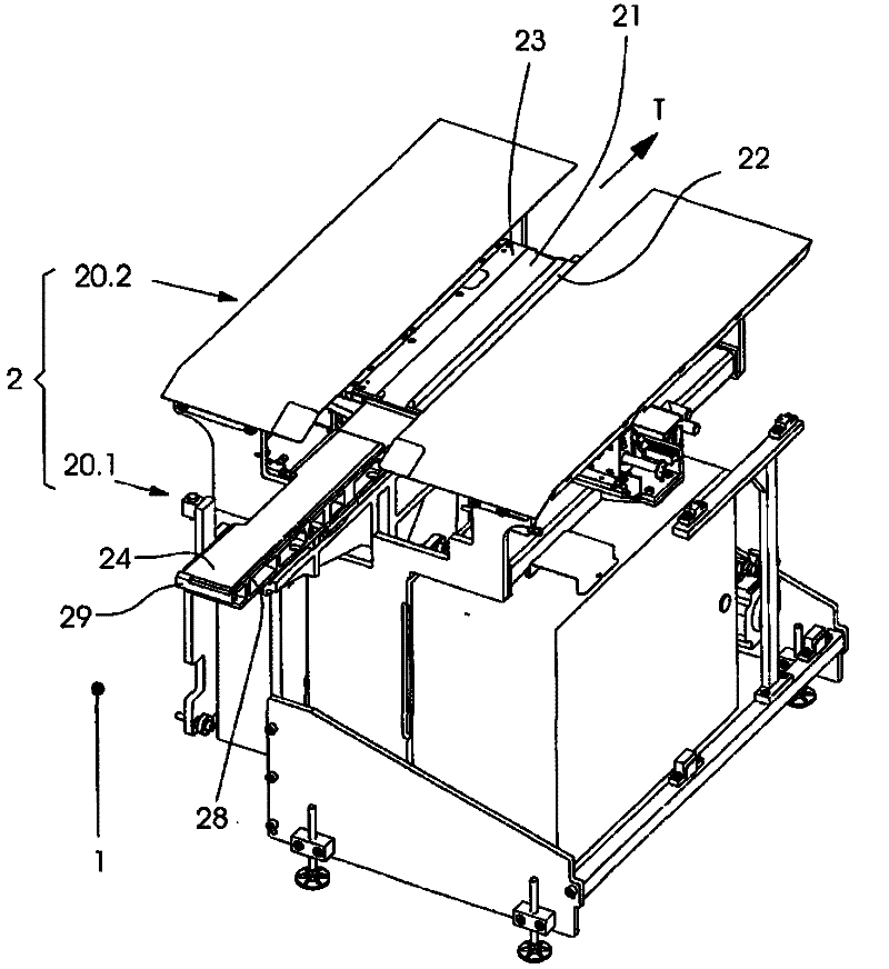
[0025] figure 1 A detail of the perfect binding machine 1000 is shown together with a part of the associated book block transport system 33 , which is formed by a driven revolving chain (not shown in detail) with clamps 1002 fastened thereto. The drive of the slewing chain is formed, for example, by a servomotor (not shown). Book blocks 100 come from a collating machine 1010 and are fed to the perfect binding machine 1000 in a transport direction T. The book block 100 is gripped by grippers 1002 and conveyed to a first processing station, the book-back processing station 1020 . The back processing station 1020 can have a plurality of processing tools not shown. The back-treated book block 100 is further transported to the gluing station 1030 and provided with adhesive material. Shielding can optionally be applied in a subsequent shielding station 1040 In the device 20.1 for laying and fixing covers, the covers 101 supplied by the cover supply station 1 are laid and fasten...


PUM


Abstract

The invention provides a device for moving a cover (101) provided by the transport system (35) of a cover feeding station (1) along the transport direction (T) and laying and aligning the cover on a printing core (100) with an adhesive layer. The device comprises a pressing bench (28) capable of moving along the vertical and horizontal directions. The pressing bench comprises a pressing surface (24) used for substantially horizontally laying and pressing a cover. The transport systems (33, 35) are driven by individual drives. The pressing bench (28) has a driver (29) protruding from the pressing surface (24).

Description

technical field [0001] The invention relates to a device for laying and orienting covers according to the preamble of claim 1 . Background technique [0002] A perfect binding machine is used to manufacture booklets or book blocks for hardcover books joined by adhesives, in which the folded sheets and / or individual pages assembled into book blocks are assembled by applying bonding material or glue to previously treated connected on the spine. Glue and bonding material are used synonymously below. Possible binding methods and production scenarios depend on machine configuration. It basically comprises functional units namely book block conveying system, book block introduction station, back handling unit, back gluing unit, intermediate drying unit, side gluing unit, back strengthening unit, laying and pressing of covers, pressing and drying of covers. [0003] Such a perfect binding machine, also known as a book binding machine, is known from DE 20 2005 007 012 U1. It has...

Claims


Application Information

Patent Timeline
IPC IPC(8): B42C11/02
CPCB65H9/14B65H9/08B42C11/04B65H9/06
Inventor R・福格特伦德
Owner MULLER MARTINI HLDG
Learn More