
Laser marking method and device adopting same

A laser marking and laser engraving technology, which is applied in the field of laser marking, can solve problems such as difficult to identify codes and the processing range cannot cover the full length

Inactive Publication Date: 2012-07-04
GEERDUN MANAGEMENT
View PDF0 Cites 0 Cited by
  • Summary
  • Abstract
  • Description
  • Claims
  • Application Information

AI Technical Summary

Problems solved by technology

However, due to the radiation source and on the one hand its radiation quality M 2 parameters and on the other hand with respect to the focal length F of mutually coordinated objectives, the processing range of known solutions cannot cover the full length of the column, so that marking can only be performed in sections
This move required a lot of effort to maintain the necessary precision of the movable components to avoid handling false passages between ranges, resulting in illegible codes

Method used


Image

  • Laser marking method and device adopting same
  • Laser marking method and device adopting same
  • Laser marking method and device adopting same

Examples


Embodiment Construction

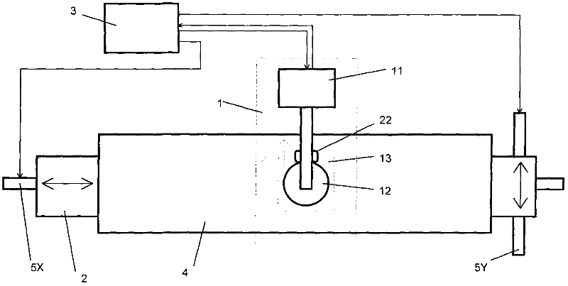
[0008] according to figure 1 A marking device according to the invention for the production of long semiconductor columns for photovoltaic cells comprises a laser inscription device 1 with a laser source 11 whose radiation emission takes place via a scanner 12 and an objective lens (not shown). The laser inscription device 1 is connected to a control computer 3 which is connected on the entry side to a detection system 22 for the actual coordinate values. The detection system 22 for the actual coordinate values ​​is arranged next to the scanner 12, but could instead be arranged at any other suitable point. The control signal of the computer 3 is put into the scanner 12, so that radiation guidance is performed inside the engraving range 13. Radiation guidance is performed in a known manner by shifting the scanner level. The introduction of the semiconductor column 4 takes place by means of a transport device 2 which can be positioned in two dimensions by means of two drives ...


PUM


Abstract

The invention relates to a laser marking method for a workpiece and a device. The workpiece is positioned in a lettering range with at least one dimension, and the lettering range is larger than a laser lettering device. The laser marking method and the device are characterized in that the workpiece is positioned in the laser lettering device in a mode, accordingly, marking initial coordinates to be applied are changed to be positioned in the lettering range of the laser lettering device, laser rays are guided within the lettering range by a laser guiding unit, and move relatively between the workpiece and the lettering range in at least one dimension, the dimensions are overlain on the laser guiding unit and are opposite to deflection of the rays in the same dimensions, after reaching final marking coordinates to be executed, the laser rays instantly stop moving between the workpiece and the lettering range, the laser guiding unit is stopped instantly, and the workpiece is taken out from the laser lettering device.

Description

technical field [0001] The invention relates to a method and a device for laser marking a workpiece which is larger in at least one dimension than the inscription range of a laser inscription device. A preferred field of application of the present invention is the marking of extended workpieces such as semiconductor rows for the production of wafers. In order to qualify the quality assurance of the production of the semiconductor columns, the semiconductor columns are provided with barcodes and test codes on the longitudinal sides. Marking by laser inscription in such a way that the thickness of the wafer after sawing becomes between 120 μm and 210 μm, the barcode is identifiable on the edge of the wafer and by means of a test code it is possible to draw information about the length along the column conclusions about the original position of the wafer. Background technique [0002] It is known to carry out the coding of the semiconductor columns by laser inscription. Howe...

Claims


Application Information

Patent Timeline
Patent Type & Authority Applications(China)
IPC IPC(8): B44B3/00
Inventor G・特绍尔M・维斯贝克
Owner GEERDUN MANAGEMENT
Learn More