Novel crane luffing mechanism

A luffing mechanism and crane technology, applied in cranes and other directions, can solve problems such as dumping, economic losses, casualties, etc., and achieve the effect of ensuring safety and ensuring safety.

Inactive Publication Date: 2012-07-04
QINGDAO PORT GRP
View PDF4 Cites 6 Cited by
  • Summary
  • Abstract
  • Description
  • Claims
  • Application Information

AI Technical Summary

Problems solved by technology

However, if there is a major fault such as high-speed shaft brake failure or gear box broken teeth or broken shaft, the high-speed shaft brake of the luffing mechanism will lose its braking effect on the wire rope drum and the boom structure, and the boom structure will lose the traction of the wire rope. , dumped under the action of its own weight, causing major safety accidents, bringing huge economic losses and casualties

Method used


Image

  • Novel crane luffing mechanism
  • Novel crane luffing mechanism
  • Novel crane luffing mechanism

Examples


Embodiment Construction

[0017] In order to make the purpose, technical solutions and advantages of the embodiments of the present invention clearer, the technical solutions in the embodiments of the present invention will be clearly and completely described below in conjunction with the drawings in the embodiments of the present invention. Obviously, the described embodiments It is a part of embodiments of the present invention, but not all embodiments. Based on the embodiments of the present invention, all other embodiments obtained by persons of ordinary skill in the art without creative efforts fall within the protection scope of the present invention.

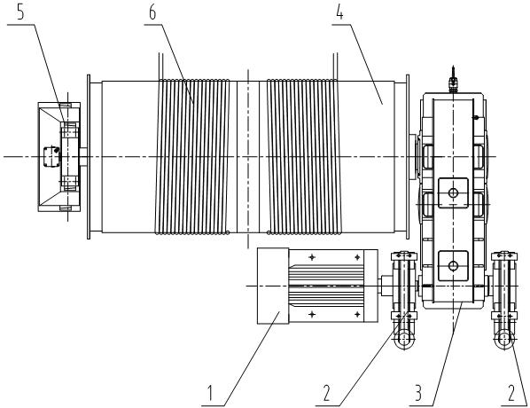
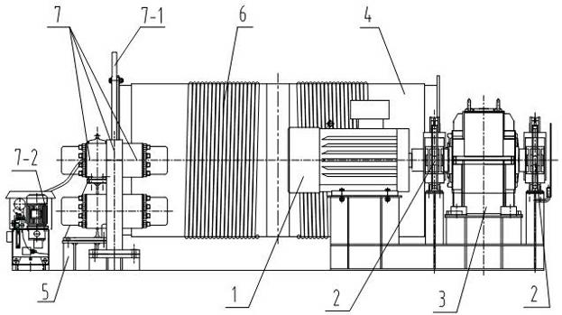
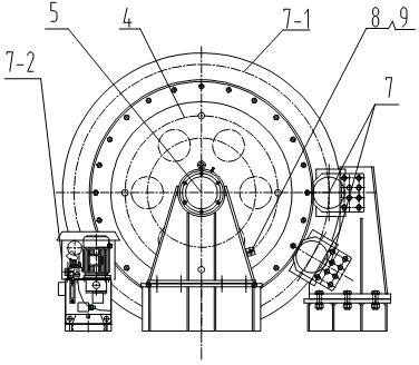
[0018] refer to figure 2 with image 3 As shown, a new type of crane luffing mechanism in this embodiment includes a motor 1, a control system, a high-speed shaft brake 2, a reduction box 3, a reel 4, a reel support 5 and a steel wire rope 6 wound on the reel 4, In order to reduce the braking torque and structural size, the brake is installed o...


PUM


Abstract

The invention provides a novel crane luffing mechanism which plays the role of double brake protection on a roller and an arm support luffing mechanism and improves the safety of a crane. The novel crane luffing mechanism comprises a motor, a control system, high-speed shaft brakes, a reduction gearbox, a winding drum, a winding drum support and a steel wire rope wound on the winding drum, wherein the high-speed shaft brakes are arranged at the two sides of the high-speed shaft end of the reduction gearbox, at least one end of the winding drum is provided with a disc type low-speed shaft brake, and a brake disc of the disc type low-speed shaft brake is fixed with the winding drum into a whole on the end face of the winding drum. According to the invention, the disc type low-speed shaft brake is additionally arranged at the end part of the winding drum, so that the disc type low-speed shaft brake can brake the winding drum and the arm support luffing mechanism when great faults such as the failure of the high-speed shaft brakes at the high-speed shaft end of the reduction gearbox, the tooth breaking of the reduction gearbox, the shaft breaking and the like, thereby ensuring the safety of the arm support luffing mechanism and the whole machine; and the rotating speed of the winding drum can be detected in real time through the arrangement of a rotating speed detector, and the wind drum can be braked quickly, so that the safety of the equipment can be ensured.

Description

technical field [0001] The invention belongs to the technical field of hoisting equipment, and relates to a crane accessory mechanism, in particular to a structural improvement of a crane luffing mechanism. Background technique [0002] When the crane lifts goods in different positions, it is necessary to use steel wire ropes to control the pitch of the jib structure to adjust the tilt angle of the jib to realize the luffing function. The mechanism that realizes the boom luffing function is called the luffing mechanism, refer to figure 1 As shown, the luffing mechanism is composed of a motor 1, a brake 2, a reduction box 3, a reel 4, a reel support 5 and a steel wire rope 6 wound on the reel 4. After the torque is applied, the rotary motion of the drum is converted into the linear motion of the steel wire rope, and the steel wire rope moves through the pulling jib structure of the pulley block to realize the luffing function of the crane. The brake is a device that deceler...

Claims


Application Information

Patent Timeline
Patent Type & Authority Applications(China)
IPC IPC(8): B66C23/82B66C23/88
Inventor 李小山李书强韩晓龙
Owner QINGDAO PORT GRP
Why Eureka
Try Eureka