
Grouted rubble and concrete combined gravity retaining wall

A technology of mortar block stone and concrete, which is applied in construction, artificial islands, infrastructure engineering, etc., can solve the problems of waste of materials and unreasonable materials for gravity retaining walls, etc., and achieve cost saving and good edge Slope support bearing capacity and low cost effect

Inactive Publication Date: 2012-07-04
CHONGQING UNIV
View PDF6 Cites 5 Cited by
  • Summary
  • Abstract
  • Description
  • Claims
  • Application Information

AI Technical Summary

Problems solved by technology

[0009] Aiming at the above-mentioned deficiencies in the prior art, the present invention solves the defects of unreasonable materials used in single-material gravity retaining walls, resulting in waste of materials and high engineering cost, and provides a significantly saved cost, more reasonable structure, and effective Combined gravity retaining wall of mortar block stone and concrete to ensure its retaining capacity

Method used


Image

  • Grouted rubble and concrete combined gravity retaining wall
  • Grouted rubble and concrete combined gravity retaining wall
  • Grouted rubble and concrete combined gravity retaining wall

Examples


Embodiment 1

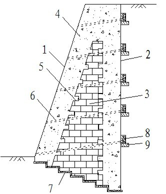
[0029] Embodiment 1: see figure 1 , a grout block stone and concrete combined gravity retaining wall, comprising a wall, the wall is composed of a grout block stone layer 3 and a concrete layer 4, the outside of the wall is a concrete layer, and the inside is a grout block Stone layer: The junction of the mortar block stone layer and the concrete layer is occluded together by the horse-tooth-shaped occlusal structure 5, which can avoid the formation of weak joints at the junction, effectively promote the synergy of the two materials, and prevent The two materials slide against each other for better stability. At the same time, only the inside is filled with mortar block stones, and the outside is made of high-strength concrete, which is suitable for slope projects with high height and high earth pressure. The bottom surface of the wall body is in a stepped shape, and its bottom surface is inclined downward along the outer side to the inner side, which can effectively improve ...

Embodiment 2

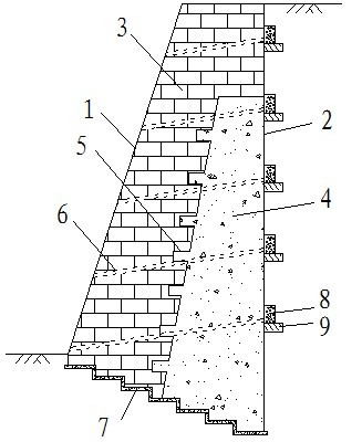
[0040] Example 2, see figure 2, and the difference from Example 1 is that the inner side (tension side) of the wall is a concrete layer 4, and the outer side (side of the free surface) is a mortar block stone layer 3. Using concrete instead of masonry blocks on the tension side of the retaining wall can effectively reduce the cross-sectional size of the original pure masonry block retaining wall. Because concrete has good performance-price ratio compared with masonry masonry in terms of tensile strength, the engineering cost of this retaining wall is lower than that of the previous pure masonry masonry retaining wall, and the bearing capacity of the retaining wall has not been weakened at the same time . At the same time, the inner side (tension side) of the wall is made of concrete material. Since the tensile strength of the mortar block stone is lower than that of concrete, the inner side (tension side) is made of concrete material when the height, width and section of the...

Embodiment 3

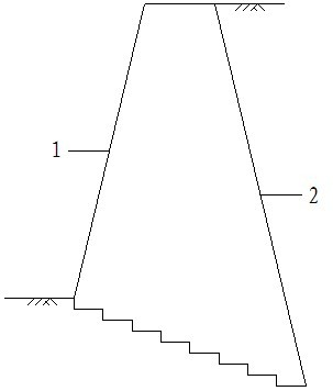
[0041] Example 3, see image 3 , the difference from Embodiment 1 or 2 is that the outer side 1 of the wall is tilted up and the inner side 2 is tilted down. The slope of the inner side of the wall is conducive to reasonably decomposing the earth pressure, increasing the anti-slip and anti-overturning stability coefficient of the retaining wall. Compared with Example 1, it is suitable for slope projects with higher height and greater earth pressure.


PUM


Abstract

The invention provides a grouted rubble and concrete combined gravity retaining wall, which comprises a wall body composed of a grouted rubble layer and a concrete layer. The grouted rubble layer and the concrete layer are connected together in a toothing structure, and drain pipes penetrating through the inner side and the outer side of the wall body are arranged inside the wall body. The concrete layer serves as the body of the wall, while the grouted rubble layer is used as inner filling, or the grouted rubble layer serves as the body of the wall, and the concrete layer is built on the tension side. The gravity retaining wall of pure concrete combined with the grouted rubber has manufacturing cost more reduced. Retaining capacity of grouted rubble retaining walls of the same sectional size can be improved evidently, stability of the walls is better, and construction convenience is not decreased for the walls. The grouted rubble and concrete combined gravity retaining wall has excellent technical progress significance and economic value in application to high-quantity large-scale slope retaining projects for water conservancy, buildings, highways and railways.

Description

technical field [0001] The invention relates to a side slope support retaining wall, in particular to a combined gravity retaining wall of mortar block stone and concrete. [0002] Background technique [0003] Gravity retaining wall is a structural type widely used in water conservancy, construction, road and railway slope support engineering. [0004] In a normal working gravity retaining wall, at any height, the tensile and compressive stresses on the cross-section are uneven, and the side close to the soil has a relatively large tensile stress, while the side close to the free surface In the wall, there is a relatively large compressive stress, and in the middle of the cross-section, there is an area where both tensile and compressive stresses are relatively small. Existing gravity type retaining walls all adopt single material to carry out construction, as concrete, mortar block stone etc. [0005] Although the pure concrete retaining wall has a strong bearing capaci...

Claims


Application Information

Patent Timeline
IPC IPC(8): E02D29/02
Inventor 曾祥勇刘晓博吴小伟
Owner CHONGQING UNIV
Learn More