Scaffold intelligent steel pipe with self-stress-monitoring function
A stress monitoring and scaffolding technology, applied in the field of scaffolding steel pipes, can solve problems such as insufficient attention to stability, potential safety hazards of scaffolding or formwork, poor structural stability of steel pipe supports, etc., achieving high practical value, flexible use, simple structure
- Summary
- Abstract
- Description
- Claims
- Application Information
AI Technical Summary
Problems solved by technology
Method used
Image

Examples
Embodiment 1
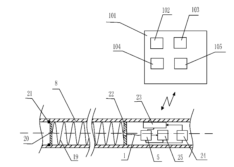
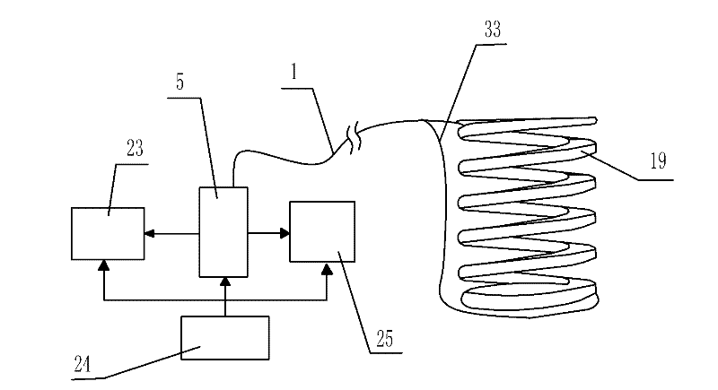
[0042] Such as figure 1 , 2 A scaffolding smart steel pipe with self-stress monitoring shown in and 3 includes a steel pipe 8, an optical fiber bending sensor unit arranged inside the steel pipe 8, a battery module 24 for supplying power to the optical fiber bending sensor unit, and a battery module located outside the steel pipe 8. And away from the control unit 101 of the steel pipe 8, the optical fiber bending sensing unit includes a curved test channel through which the signal optical fiber 33 passes, and the signal optical fiber 33 is connected to the signal optical fiber 33 and changes the optical signal power in the signal optical fiber 33. A test processing unit 5 for synchronous testing and analysis processing. The test processing unit 5 is also connected to a wireless transceiver module 25 and an alarm module 23 in the form of sound or vibration. The alarm module 23 is located inside the steel pipe 8. The processing unit 5 is also connected to the battery module 24, an...
Embodiment 2
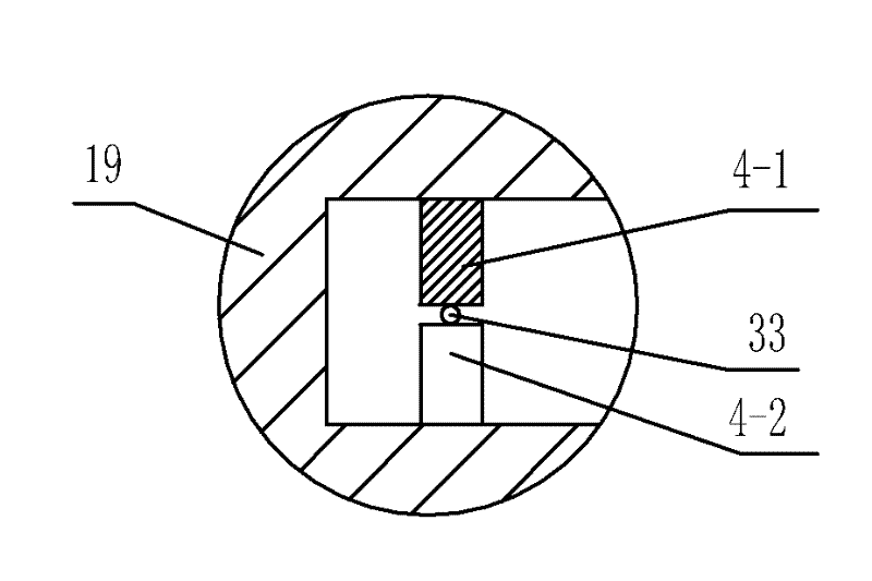
[0049] Such as Figure 4 As shown, the difference between this embodiment and Embodiment 1 is that the curved support 10 is a spring 38, and a plurality of deforming teeth 4-1 and a plurality of deforming teeth 4-2 are arranged correspondingly in the spring 38 and adjacent to each other. Between the coils of spring wires, deformed tooth 4-1 and deformed tooth 2 4-2 are arranged alternately. In this embodiment, the structure, connection relationship and working principle of the remaining parts are the same as those in the first embodiment.
Embodiment 3
[0051] Such as Figure 5 with 6 As shown, the difference between this embodiment and Embodiment 1 is that the curved support 10 is a corrugated tube 40, and the deforming tooth 4-1 and the deforming tooth 2 4-2 are correspondingly arranged on the tube wall 42 of the corrugated tube 40 On the two opposite sides of the recess, deformed tooth 4-1 and deformed tooth 2 4-2 are arranged alternately. In this embodiment, the structure, connection relationship and working principle of the remaining parts are the same as those in the first embodiment.
PUM
 Abstract
Description
Claims
Application Information
 - R&D Engineer
- R&D Manager
- IP Professional
- Industry Leading Data Capabilities
- Powerful AI technology
- Patent DNA Extraction
Browse by: Latest US Patents, China's latest patents, Technical Efficacy Thesaurus, Application Domain, Technology Topic.
© 2024 PatSnap. All rights reserved.Legal|Privacy policy|Modern Slavery Act Transparency Statement|Sitemap