
Pull type rotating double-layer parking device

A double-deck parking and one-to-one technology, which is applied in the direction of buildings, building types, and buildings where cars are parked, can solve the problems that the utilization efficiency of parking spaces cannot reach 100%, that cars cannot be picked up and picked up at will, and the structure is complex, etc., to achieve The effect of simple rotation and operation, simple structure and simple method

Active Publication Date: 2012-07-04
佛山市洋德自动化机械设备有限公司
View PDF13 Cites 10 Cited by
  • Summary
  • Abstract
  • Description
  • Claims
  • Application Information

AI Technical Summary

Problems solved by technology

This kind of double-deck parking device has a complex structure, and it must have more than two rows of parking spaces to operate normally. During normal operation, one parking space must be empty, and the utilization efficiency of parking spaces cannot reach 100%.
Even the simple double-deck parking equipment cannot pick up and pick up the car at will. It is extremely inconvenient to access the upper floor only after the car on the lower floor is driven away.

Method used


Image

  • Pull type rotating double-layer parking device
  • Pull type rotating double-layer parking device
  • Pull type rotating double-layer parking device

Examples


Embodiment Construction

[0027] Now in conjunction with accompanying drawing and embodiment the present invention is described in further detail:

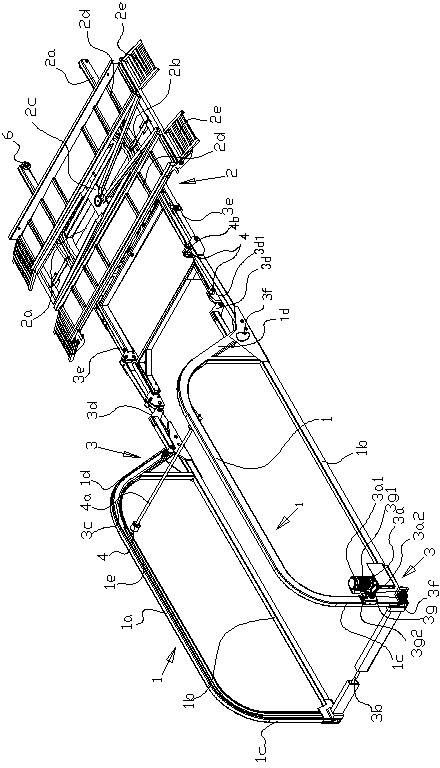
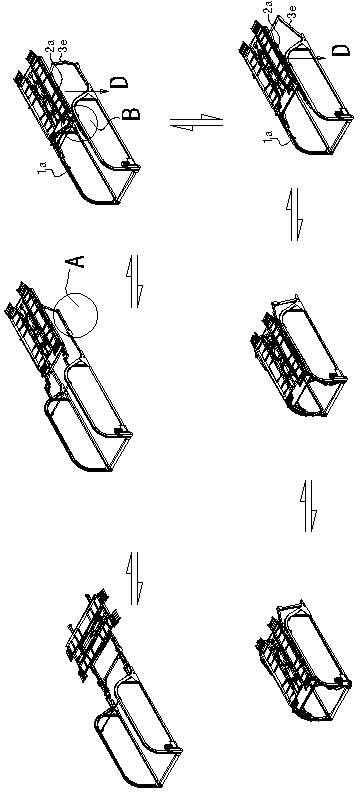
[0028] Such as figure 1 As shown, the present invention comprises a pair of parallel frame 1, motion platform 2, transmission mechanism 3, and motion platform 2 comprises seat 2a, the platform 2b that rotation is arranged on seat 2a, the power unit 2c that drives platform 2b to rotate, on platform 2b Two parallel passages 2d are set, and the two ends of the passage 2d are provided with slopes 2e which are convenient for the wheels to enter and exit. 1d, the cross section of the frame 1 is a horizontal C-shaped groove 1e, the transmission mechanism 3 includes a power mechanism 3a, a pair of synchronous belts 3c driven by the power mechanism 3a through the synchronous pulleys 3f at both ends of the rotating shaft 3b, and a pair of synchronous belts 3c driven respectively A pair of tie rods 3d and a pair of link mechanisms 3e, several synchronous whe...


PUM


Abstract

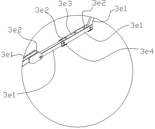
A double-layer parking device is characterized by comprising a pair of parallelly arranged frames, a movement platform and a transmission mechanism. The movement platform comprises a seat, a platform rotatably arranged on the seat and a power device driving the platform to rotate. The pair of frames comprises an upper beam and a lower beam, a front vertical column and a rear vertical column, wherein the front vertical column and the rear vertical column are connected to two ends of both the upper beam and the lower beam. The section of the frames is in a horizontal C-shaped groove shape. The transmission mechanism comprises a power mechanism, a pair of synchronous belts driven by the power mechanism, a pair of pull rods and a pair of connecting rod mechanisms, wherein the pull rods are respectively driven by the pair of synchronous belts. A plurality of synchronous wheels are arranged on the lower beam arranged at the bottoms of the frames, the synchronous belts are arranged on the synchronous wheels, each connecting rod mechanism is two connecting rods, three connecting rods, four connecting rods or five connecting rods, one ends of the connecting rod mechanisms are hinged to the outer sides of the bottoms of the frames, and the other ends of the connecting rod mechanisms are hinged to the side portion of the seat. A limiting check block limiting connecting rods so as to enable the connecting rods to swing upwards for below 90 degrees from a horizontal state is arranged adjacent two connecting rods of the connecting rod mechanisms, and a pulley is arranged on the upper beam of the frames or at the position located below the seat opposite to the frames. Compared with the prior art, the double-layer parking device has the advantages of being simple in structure, being capable of meeting parking requirements of various fields, and enabling carport utilizing rate to reach 100%.

Description

technical field [0001] The invention relates to a parking device. Background technique [0002] Existing double-deck parking device is generally made up of multiple parking spaces up and down, each pair of upper and lower parking spaces has a lift, and each floor of parking spaces has a lateral movement mechanism. When parking, one parking space must be vacant so that the car can come out from the parking space . This kind of double-deck parking device has complex structure, and must have more than two rows of parking spaces to operate normally. During normal operation, one parking space must be empty, and the parking space utilization efficiency can not reach 100%. Even the simple type double-deck parking equipment can not pick up the car and get the car at will. It is extremely inconvenient to access the upper floor after the car on the lower floor has to be driven away. Contents of the invention [0003] The object of the present invention is to provide a double-deck ...

Claims


Application Information

Patent Timeline
IPC IPC(8): E04H6/06
Inventor 何甜灶何泽贤
Owner 佛山市洋德自动化机械设备有限公司
Learn More