Sidelight type backlight source module

A backlight and edge-light technology, applied in the field of edge-light backlight modules, can solve problems such as uneven light output

Inactive Publication Date: 2012-07-04
EPILIGHT TECH +1
View PDF3 Cites 47 Cited by
  • Summary
  • Abstract
  • Description
  • Claims
  • Application Information

AI Technical Summary

Problems solved by technology

[0006] The purpose of the present invention is to provide a side-lit backlight module, especially an arrangement design of the dots of the lig

Method used


Image

  • Sidelight type backlight source module
  • Sidelight type backlight source module
  • Sidelight type backlight source module

Examples


no. 1 example

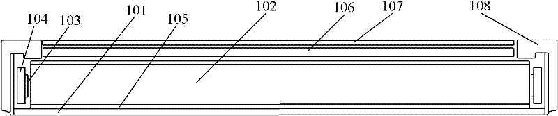
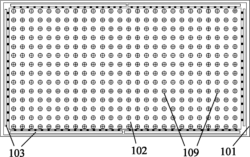
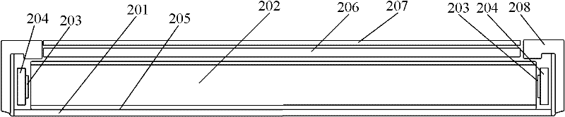
[0030] see image 3 and Figure 4 ,in image 3 It shows the side sectional view of the edge-lit backlight module of the present invention in the first embodiment, Figure 4 shown image 3 The top view of the edge-lit backlight module. combine image 3 and Figure 4 , the side-lit backlight module includes: a light source bracket composed of a backplane 201 and a plastic frame 208; a light guide plate 202 is arranged inside; A plurality of LED light sources are arranged on the strip 203 on a printed circuit board (PCB) 204 behind it; a reflective film 205 is provided under the light guide plate 202 . In practical applications, the LED light bar 203 emits light, and the light guide plate 202 is used to introduce light from the edge to the central area of ​​the display screen, so that the entire display screen has enough backlight to allow the LCD screen to display images. Of course, in addition to this, the side-lit backlight module also includes other components, for exa...

no. 2 example

[0041] see Figure 5 and Figure 6 ,in Figure 5 It shows a side sectional view of the edge-lit backlight module of the present invention in the second embodiment, Figure 6 shown Figure 5 The top view of the edge-lit backlight module. to combine Figure 5 and Figure 6 , the side-lit backlight module includes: a light source bracket composed of a backplane 301 and a plastic frame 308; a light guide plate 302 is arranged inside; A LED light source is arranged on the printed circuit board 304 thereafter; a reflective film 305 is arranged under the light guide plate 302; Membrane group.

[0042] Compared with the design in the first embodiment in which LED light bars 203 are provided on two opposite sides of the light guide plate 202 , in the second embodiment, the LED light bar 303 is only provided on one side of the light guide plate 302 . Therefore, the light-incident bottom surface of the light guide plate 302 is provided with non-uniformly arranged scattering dots ...


PUM

PropertyMeasurementUnit
Sizeaaaaaaaaaa
Diameteraaaaaaaaaa
Heightaaaaaaaaaa

Abstract

The invention provides a sidelight type backlight source module which comprises a light source bracket with a back plate and a rubber frame, LED (Light-Emitting Diode) lamp strips with a plurality of LED light sources, a printed circuit board, a reflecting film, a light guide plate, a brightening film and a scattering film. The light guide plate comprises a light incident bottom surface and a light emergent top surface which is opposite to the light incident bottom surface; scattering lattice points are arranged on the light incident bottom surface of the light guide plate; a gradual change type arrangement way in which the arrangement density degree is determined according to the distances from the scattering lattice points to the LED light sources is adopted for the scattering lattice points; and the arrangement density gradually increases along with the increase of the distances from the scattering lattice points to the LED light sources by regarding the LED lamp strips as boundaries. Compared with the prior art, the sidelight type backlight source module disclosed by the invention provides a backlight source by placing the LED strips at the two sides or single side and changes emergent light brightness at each special position of the light guide plate by setting the non-uniformly distributed scattering lattice points, so that light reinforcement is realized at corresponding position of the light guide plate, which is far away from the LED light sources, and thus ideal light brightness and light emergent uniformity are obtained through the light guide plate.

Description

technical field [0001] The invention relates to a liquid crystal display device, in particular to a side-light type backlight source module which adopts an LED light source and is applied to a liquid crystal display device. Background technique [0002] At present, a liquid crystal display device (Liquid Crystal Display hereinafter referred to as LCD) has become the mainstream in the field of flat panel display. Since the LCD screen itself does not emit light, the backlight module is one of the key components of the LCD. The function of the backlight module is to provide a light source with sufficient brightness and uniform distribution so that it can display images normally. The current LCD backlight is mainly cold cathode tube CCFL and light emitting diode LED. As a new type of backlight, LED has many obvious advantages compared with the traditional CCFL backlight: LED backlight has a better color gamut, the internal driving voltage of LED is much lower than that of CCFL,...

Claims


Application Information

Patent Timeline
IPC IPC(8): F21S8/00F21V8/00F21V19/00G02F1/13357F21Y101/02
Inventor 范曼宁郝茂盛陈云峰张义荣张洋张黎鑫
Owner EPILIGHT TECH
Why Eureka
Try Eureka