Central diffusion type tiny-oil ignition combustor

A micro-oil ignition and diffusion technology, which is applied to burners, burners for burning powder fuel, combustion methods, etc., can solve the problem of reducing the burnout rate of pulverized coal at the burner outlet, the long size of the pulverized coal burner, and the reduction of ignition stability. It can achieve the effect of good cooling, ensuring safety and improving ignition efficiency.

Inactive Publication Date: 2012-07-04
CHINA JILIANG UNIV
View PDF6 Cites 15 Cited by
  • Summary
  • Abstract
  • Description
  • Claims
  • Application Information

AI Technical Summary

Problems solved by technology

Chinese patents ZL03255982.8, ZL200520145352.2, ZL200710156019.5, etc. have announced several different forms of micro-oil ignition burners, and these burners have their own advantages in realizing micro-oil ignition and low-load stable combustion; The arrangement of oil guns adopted by the burner makes the heating of pulverized coal by the high-temperature flame either single-point heating or multi-point heating, which results in long heating time and requires a long size of the entire pulverized coal burner
This is difficult for quite a lot of power plants, which will lead to a reduction in the burnout rate of pulverized coal at the outlet of the burner; this will greatly reduce the stability of ignition, and even lead to failure of normal ignition

Method used


Image

  • Central diffusion type tiny-oil ignition combustor
  • Central diffusion type tiny-oil ignition combustor
  • Central diffusion type tiny-oil ignition combustor

Examples


Embodiment Construction

[0012] The present invention will be further described below in conjunction with the accompanying drawings and embodiments.

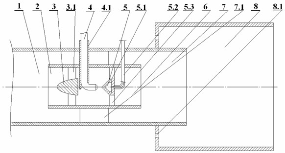
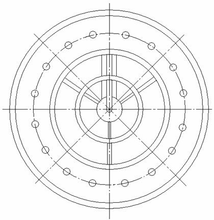
[0013] like figure 1 , figure 2 As shown, the present invention includes a main primary air duct 1, an inner primary air duct 2, a pulverized coal concentration cone 3, an L-type ignition oil gun 4, a controllable vortex flame spreading blunt body 5, and a three-stage pulverized coal combustion chamber 8; The primary air duct 2 is installed in the main primary air duct 1, a section of the main primary air duct 1 extends into the third-stage pulverized coal combustion chamber 8, and in the inner primary air duct installed in the other section of the main primary air duct 1, along the The fluid flow direction is equipped with pulverized coal concentration cone 3 and controllable vortex flame spreader blunt body 5, main primary air duct 1, inner primary air duct 2, coal powder concentration cone 3, controllable vortex flame spreader blunt body 5, and thr...


PUM


Abstract

The invention discloses a central diffusion type tiny-oil ignition combustor. An inner primary air pipe is mounted in a main primary air pipe, one section of the main primary air pipe extends into a tertiary pulverized coal combustion chamber, another section of the main primary air pipe is mounted in the inner primary air pipe, a pulverized coal concentration cone and a vortex-controllable flameexpanding blunt body are sequentially mounted in the inner primary air pipe along a flowing direction of fluid, and are coaxially installed; a small section of an L-shaped ignition oil gun in an abrasion-resistant sleeve is aligned with a cone of the vortex-controllable flame expanding blunt body, a small section of an L-shaped air inlet pipe is aligned with the bottom end of the vortex-controllable flame expanding blunt body in a hollow structure, air outlet holes are circumferentially uniformly distributed at the bottom end of the vortex-controllable flame expanding blunt body, and a plurality of circular secondary air inlet holes are equidistantly arranged on a closed end surface of the tertiary pulverized coal combustion chamber. High-temperature flame ejected by the ignition oil gun is ejected onto the flame expanding blunt body, and is obliquely diffused along the outer edge of the blunt body to a wall surface of a round pipe, ignition around a ring surface is realized, and ignition efficiency is greatly improved. In addition, the vortex-controllable flame expanding blunt body can control the size of a high-temperature backflow area formed at an outlet of a primary combustion chamber, so that fuel adaptability can be enhanced.

Description

technical field [0001] The invention relates to a pulverized coal burner, in particular to a center diffused micro-oil ignition burner. Background technique [0002] The conventional method for boiler start-up and low-load stable combustion in a thermal power station is to use a large oil gun to inject oil into the furnace and support combustion. Depending on the furnace type, 50-200 tons of fuel oil needs to be put in during the cold start of the boiler from ignition to pulverized coal feeding with load. With the use of micro-oil ignition and combustion-supporting technology, according to the principle of step-by-step energy amplification, a small amount of pulverized coal can be directly ignited with a high-energy oil gun, and then more pulverized coal can be ignited step by step; thus, a small amount of oil can be used to start the cold furnace of the boiler. According to different types of coal, the oil saving effect can generally reach 60-98%. At present, my country h...

Claims


Application Information

Patent Timeline
Patent Type & Authority Applications(China)
IPC IPC(8): F23D1/00
Inventor 闫志勇潘江珊丹
Owner CHINA JILIANG UNIV
Why Eureka
Try Eureka