Heat collecting system with double-row solar vacuum tube matrix

A technology of solar energy and vacuum tubes, applied in the field of solar energy, can solve problems such as inability to obtain high-quality heat energy, inability to apply solar vacuum heat collection systems, and inability to achieve solar energy utilization

Active Publication Date: 2012-07-04
卓卫民
View PDF10 Cites 0 Cited by
  • Summary
  • Abstract
  • Description
  • Claims
  • Application Information

AI Technical Summary

Problems solved by technology

[0013] The technical problem to be solved by the present invention is that the solar vacuum tubes in the prior art are fully connected in series or in parallel, or connected in series within a group and then connected in parallel, which cannot be applied to large-scale solar vacuum heat collection systems, and cannot obtain high-quality The thermal energy can not achieve the improvement of solar energy utilization rate, and then provide a solar vacuum heat collector that can obtain a medium with a higher temperature and has a high utilization rate of solar energy

Method used


Image

  • Heat collecting system with double-row solar vacuum tube matrix
  • Heat collecting system with double-row solar vacuum tube matrix
  • Heat collecting system with double-row solar vacuum tube matrix

Examples


Embodiment 1

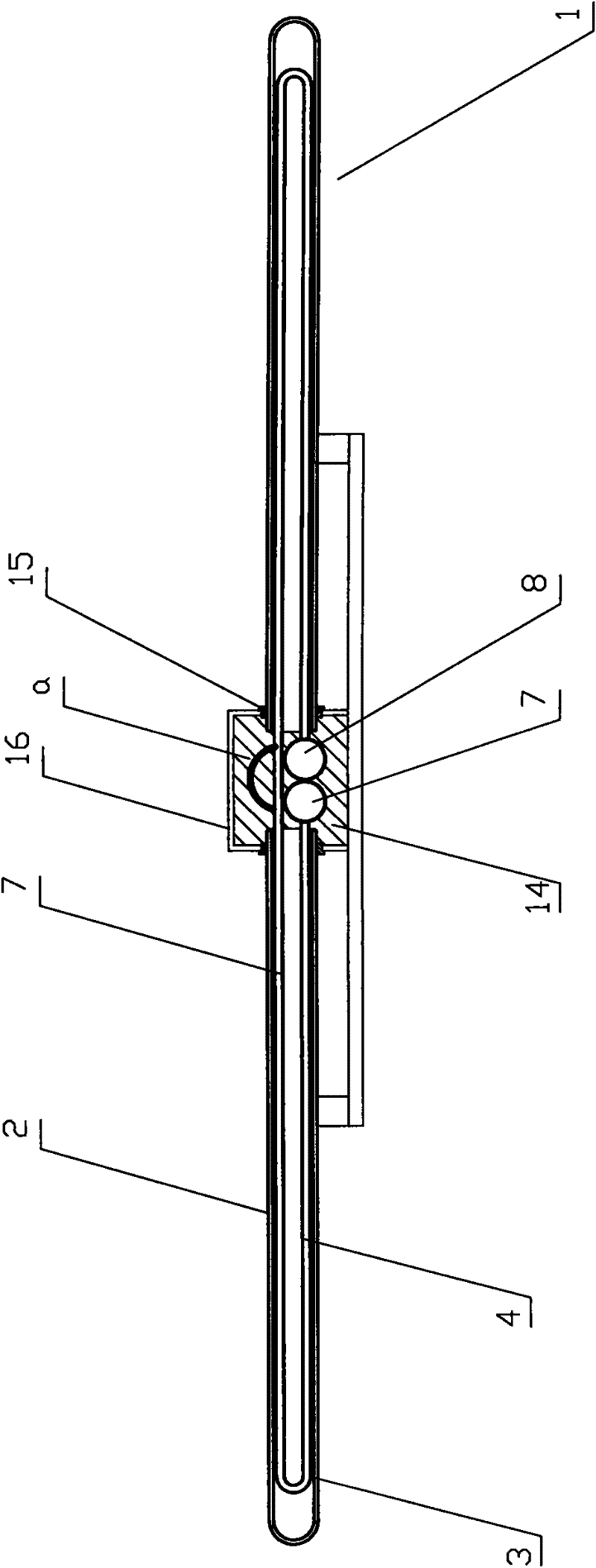
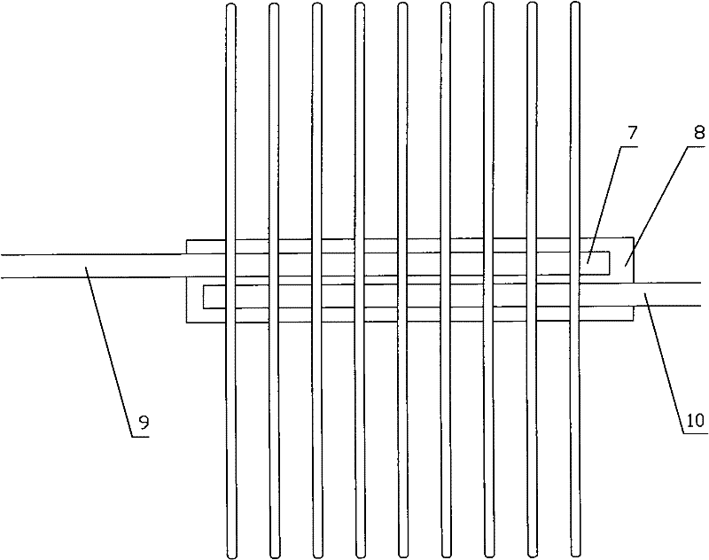
[0056] Figure 4 Shown is the front view of the solar vacuum tube matrix heat collection system of the present invention, it can be seen from the figure that the solar vacuum tube pairs 1 are neatly arranged in a matrix, wherein the structure of the solar vacuum tube pairs 1 is shown in figure 1 As shown, it consists of two solar vacuum tubes in series, the medium outlet of the U-shaped metal heat-conducting tube of the first solar vacuum tube is connected to the medium inlet of the U-shaped metal heat-conducting tube of the second solar vacuum tube connected to it, so that The series connection of the two solar vacuum tubes is realized by connecting the U-shaped metal heat-conducting tubes; the U-shaped metal heat-conducting tubes connected together of the two solar vacuum tubes have an included angle of α, wherein α is less than or equal to 180 °; the U-shaped metal heat pipe is inverted, and the glass outer tube 2 and glass inner tube 3 nested together are used to cover the...

Embodiment 2

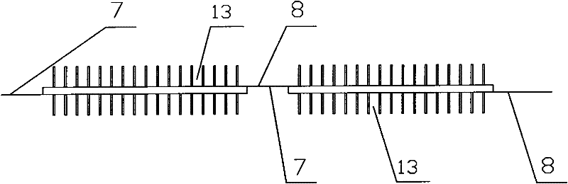
[0066] In this embodiment, a solar vacuum tube unit is also set between the water inlet main pipe 5 and the water outlet main pipe 6, and 250 solar vacuum tube tube groups 13 are arranged in the solar vacuum tube unit, and each solar vacuum tube tube The groups 13 all have a water inlet main pipe 7 and a water outlet main pipe 8, and 250 solar vacuum tube groups 13 are connected in series. When connecting, the water inlet main pipe 7 of the first solar vacuum tube group 13 is connected with the water inlet main pipe 5, Along the flow direction of the medium, the water outlet main pipe 8 of the 250th solar vacuum tube group 13 is connected to the water outlet main pipe 6 . In addition, along the flow direction of the medium, the water outlet main pipe 8 of the first solar vacuum tube group 13 is connected to the water inlet main pipe 7 of the second solar vacuum tube group 13 adjacent to it, and so on, the 249th The water outlet main pipe 8 of the solar vacuum tube group 13 is ...

Embodiment 3

[0072] In this embodiment, a solar vacuum tube unit is also set between the water inlet main pipe 5 and the water outlet main pipe 6, and 150 solar vacuum tube tube groups 13 are arranged in the solar vacuum tube 1 unit, and each solar vacuum tube The tube groups 13 all have a water inlet main pipe 7 and a water outlet main pipe 8, and 150 solar vacuum tube groups 13 are connected in series. When connecting, the water inlet main pipe 7 of the first solar vacuum tube group 13 is connected to the water inlet main pipe 5 , along the flow direction of the medium, the water outlet main pipe 8 of the 150th solar vacuum tube group 13 is connected to the water outlet main pipe 6 . In addition, along the flow direction of the medium, the water outlet main pipe 8 of the first solar vacuum tube group 13 is connected to the water inlet main pipe 7 of the second solar vacuum tube group 13 adjacent to it, and so on, the 149th The water outlet main pipe 8 of the solar vacuum tube group 13 is...


PUM

PropertyMeasurementUnit
Outer diameteraaaaaaaaaa
The inside diameter ofaaaaaaaaaa

Abstract

The invention discloses a heat collecting system with a solar vacuum tube matrix. The heat collecting system comprises a water inlet main pipe, a water outlet main pipe and W solar vacuum tube units in parallel connection, wherein a medium can flow in the water inlet main pipe and the water outlet main pipe; each solar vacuum tube unit is respectively arranged between the water inlet main pipe and the water outlet main pipe and comprises solar vacuum tube sets connected in series, a medium conveying pump and a temperature sensor; each solar vacuum tube unit is internally provided with M solar vacuum tube pairs in parallel connection and is connected with an adjacent solar vacuum tube set through the water inlet main pipe and the water outlet main pipe, and each vacuum tube pair comprises two solar vacuum tubes in which U-shaped metal tubes are connected in series. Through utilizing the heat collecting system of the solar vacuum tube matrix, disclosed by the invention, heat can be efficiently acquired at a low cost; and the heat collecting system disclosed by the invention is suitable for the fields of industrial production, urban heat supply, thermal power generation and the like.

Description

technical field [0001] The invention relates to a solar vacuum tube matrix heat collection system, which belongs to the technical field of solar energy. Background technique [0002] Today's society advocates sustainable development, among which energy issues are the key issues restricting the sustainable development of human beings. As a source of energy, solar energy is inexhaustible and inexhaustible. The amount of solar radiation received by the earth every year is tens of thousands of times the total energy consumption of human beings. If this part of energy can be fully converted and utilized, it will be It will provide energy security for the sustainable development of mankind. Although a large number of R&D personnel have devoted a lot of creative labor to the utilization of solar energy, due to the low energy density and low quality of solar energy that humans can receive, it is still very difficult to directly utilize it on a large scale. [0003] At present, rel...

Claims


Application Information

Patent Timeline
IPC IPC(8): F24J2/05F24J2/24F24J2/40F24J2/30F24J2/48F24S10/30F24S10/40F24S10/70
CPCY02E10/44Y02P80/20
Inventor 卓卫民左丽卓宇轩袁儒正张亮魏稳高科熊一峰
Owner 卓卫民
Why Eureka
Try Eureka