Ultrathin heat pipe and manufaturing method thereof

A technology of ultra-thin heat pipes and manufacturing methods, applied in the field of heat pipes, can solve problems such as insufficient working fluid gaseous circulation space, affect heat dissipation performance, poor reliability, etc., achieve good heat conduction efficiency and stability, and improve heat conduction efficiency.

Active Publication Date: 2013-10-23
ZHONGSHAN WEIQIANG TECH CO LTD
View PDF5 Cites 3 Cited by
  • Summary
  • Abstract
  • Description
  • Claims
  • Application Information

AI Technical Summary

Problems solved by technology

[0004] The ultra-thin heat pipe is designed for similar situations. The thickness of the ultra-thin heat pipe is required to be very thin, and the size is mostly 0.8-1.5mm. This will result in a very small space in the inner cavity of the heat pipe, and insufficient circulation space for the working fluid and its gaseous state. affect thermal performance
In addition, due to the size limitation of the ultra-thin heat pipe, the tube wall also needs to be made very thin, usually less than 0.3mm, and the yield rate is very low. During the manufacturing process, the process is difficult, and in the heat pipe sintering process, the sintering temperature of the copper heat pipe About 900-950 ℃, the thin tube wall is easy to produce such as Figure 22 The crystallization shown above, especially the longer the high temperature lasts, the more serious the crystallization will be, and the structure between the crystals may be weakened during the follow-up process, resulting in gaps, resulting in leakage of internal working fluid and water vapor, resulting in a significant reduction in heat pipe power; In addition, in the process of pressing and folding, the thinner tube wall is easily weakened due to deformation, and these weaker parts are easily damaged, and the reliability is poor

Method used


Image

  • Ultrathin heat pipe and manufaturing method thereof
  • Ultrathin heat pipe and manufaturing method thereof
  • Ultrathin heat pipe and manufaturing method thereof

Examples


Embodiment Construction

[0074] The idea, specific structure and technical effects of the present invention will be clearly and completely described below in conjunction with the embodiments and accompanying drawings, so as to fully understand the purpose, features and effects of the present invention. Apparently, the described embodiments are only some of the embodiments of the present invention, rather than all of them. Based on the embodiments of the present invention, other embodiments obtained by those skilled in the art without creative efforts belong to The protection scope of the present invention.

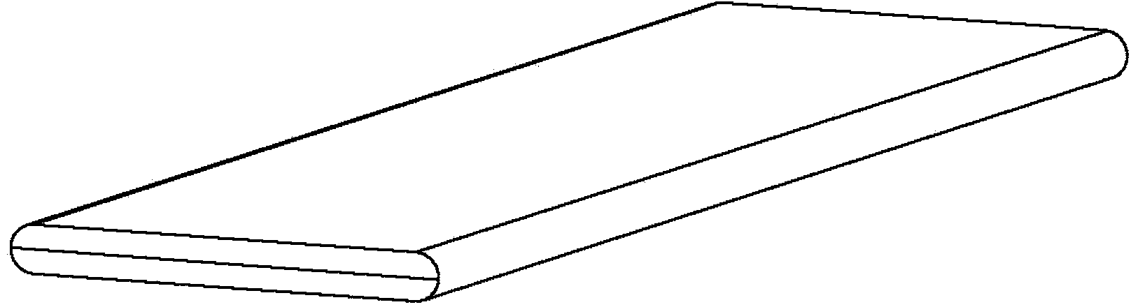
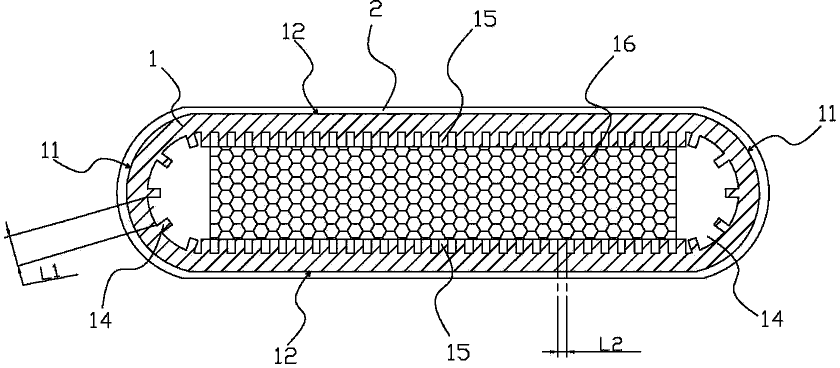
[0075] refer to figure 1 , figure 2 , the ultra-thin heat pipe provided by the present invention mainly includes a tube body 1, which is compressed into a flat shape, thereby forming a symmetrical compression section 11 and a flat section 12; both ends of the tube body 1 are sealed, and the two sealed ends are matched. The wall surface of the pipe body 1 forms a closed cavity 13; the closed ca...


PUM

PropertyMeasurementUnit
thicknessaaaaaaaaaa
thicknessaaaaaaaaaa
thicknessaaaaaaaaaa

Abstract

The invention discloses an ultrathin heat pipe, comprising a flat pipe body formed by pressing. The pipe body is provided with a compression section and a smooth section; the two ends of the pipe body are sealed to form a sealed inner cavity; working solution is filled in the sealed inner cavity, the pipe body is wrapped with a nanometer metal layer, a first groove part and a second groove part are formed in the sealed inner cavity of the pipe body, and a powder sintering part is adhered on the second groove part; and the groove density of the first groove part is smaller than that of the second groove part. The invention also provides a machining method of the ultrathin heat pipe. For the ultrathin heat pipe provided by the invention, the size of the ultrathin heat pipe can be small enough, simultaneously, the heat conduction efficiency and the stability of the ultrathin heat pipe can be guaranteed, and the matched machining method is provided; and the ultrathin heat pipe can be suitable for the various fields with good heat dissipation and limited size.

Description

technical field [0001] The invention relates to a heat pipe, in particular to an ultra-thin heat pipe and a manufacturing method thereof. Background technique [0002] Because of its ultra-high heat conduction efficiency, heat pipes are widely used in various fields that require good heat dissipation. The conventional heat pipe structure is mainly a closed metal tube with a capillary structure inside the tube and filled with an appropriate amount of working fluid. When used with a heat source, the heat of the heat source is transferred to one end of the heat pipe, and the working fluid in the tube absorbs heat and vaporizes. Under the action of pressure difference, the high-speed flow flows to the other end, releases latent heat to the cold source and condenses. Under capillary action, the condensed liquid uses the capillary structure to return from the cold source to the heat source. In this way, the heat is efficiently and quickly transferred from the heat source to the co...

Claims


Application Information

Patent Timeline
Patent Type & Authority Patents(China)
IPC IPC(8): F28D15/04B23P15/26B22F5/12
CPCF28D15/0233F28D15/046
Inventor 李克勤陈宏杰
Owner ZHONGSHAN WEIQIANG TECH CO LTD
Why Eureka
Try Eureka