Wide-range precise measuring circuit for resistance of nano sensor and method

A resistance measuring instrument and sensor technology, applied in the direction of measuring electrical variables, measuring resistance/reactance/impedance, measuring devices, etc., can solve the problems of unrealistic measurement, error of measurement results, low accuracy of measurement results, etc., and achieve the solution of zero point and its Dynamic drift, the effect of improving measurement accuracy

Inactive Publication Date: 2012-07-04
BEIJING ZHONGKE MICRO NANO NETWORKING SCI TECH
View PDF9 Cites 13 Cited by
  • Summary
  • Abstract
  • Description
  • Claims
  • Application Information

AI Technical Summary

Problems solved by technology

This method of measurement leads to five major problems in the industry and causes great errors in measurement results:
[0003] First, the accuracy of the measurement results is low. The result of the voltage division directly leads to a 50% reduction in the accuracy of the A / D conversion, and the sensitivity of the current nanosensor has reached dozens or even hundreds of times. The measurement in this way leads to such a large dynamic swing. If the measurement error is 1% before the reaction, but if the reaction sensitivity is 100, the measurement error after the reaction will be as high as 1%*100=100%, so the measurement accuracy is very low, far lower than the Nominal full-scale accuracy;
[0004] The second is that the resistance value range of the nanometer sensor is extremely wide, as large as more than gigaohms. It is necessary to choose a precision reference resistor of up to gigabytes for measurement with this voltage division method, while the range of conventional precision resistors is limited to less than 2 megohms. Precision resistors with large resistance values ​​cannot actually be made or must be made with extremely expensive materials and special processes, so measurement cannot be realized;
[0005] The third is the uncertainty of the sensor measurement voltage, that is to say, if the 5V voltage is used for measurement, the actual voltage applied to the sensor is a dynamic uncertain value, and the measurement results of this instrument will directly mislead the research results and direction of the nanosensor experiment ;
[0006] Fourth, the measurement voltage of the sensor cannot be set arbitrarily, that is, it cannot be too small or greater than the reference voltage of the A / D converter, otherwise it will cause distortion or inaccurate small-amplitude partial voltage values, which will directly lead to low accuracy of measurement results;
[0007] Fifth, the entire industry has been misled to believe that the sensitivity value of the measurement is the ratio of the partial pressure value of the measurement before and after the sensor reacts. In fact, they are quite different. It can be known through simple calculations that if the response sensitivity is m, in the best matching In the case, the voltage ratio before and after the reaction V RL2 / V RL1 =(m+1) / 2, only when m=1, the voltage ratio V RL2 / V RL1 =1=m, if m=100 then the voltage ratio V RL2 / V RL1 =50.5, it can be seen that the error of using the voltage ratio to reflect the sensitivity is unexpectedly large, which directly misleads the research of nanosensors

Method used


Image

  • Wide-range precise measuring circuit for resistance of nano sensor and method
  • Wide-range precise measuring circuit for resistance of nano sensor and method
  • Wide-range precise measuring circuit for resistance of nano sensor and method

Examples


Embodiment Construction

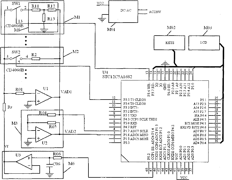
[0041] figure 2 It is a typical implementation case of a sensor resistance measuring instrument and method of the present invention, as follows:

[0042] (1) This program is implemented with an ordinary single-chip microcomputer U4 of the model STC12C5A16S2 as the core. Configurations such as the port line and the software program memory of 16KB FLASH can meet the requirements of the present invention.

[0043] (2) The test voltage source M6 is output by the operational amplifier U3, and U3 is connected as a high-impedance input voltage follower, so the test voltage source comes from a low-pass filter composed of R06 and C06, and the signal of the low-pass filter comes from a single-chip microcomputer U4 Root PWM pulse width modulation signal output port line P1.4. VT is used as the input signal voltage of the test sensor resistance, and the size of the test voltage source is controlled by the single-chip microcomputer U4 through the pulse width modulation signal. PWM is a...


PUM


Abstract

A sensor resistance measurer consists of a power module, a keyboard module, a display module, a testing voltage source, a to-be-measured sensor, an operational amplifier, a feedback network, a polarity processing module, an A / D (analog / digital) converter and a numerical value processor. At least two feedback units are connected in parallel to form the feedback network. A sensor resistance measuring method is realized by the aid of measurement initialization, A / D conversion, polarity processing, automatic gear control, automatic zero point calibration and sensor resistance calculating software. A method for obtaining high precise resistance values includes that an attenuation type feedback network of a conventional precise-resistance-value resistor is adopted in a measuring amplifier, so that precise equivalent feedback resistance with the quite high value is obtained. The sensor resistance measurer and the method have the advantages that a high-resistance-value nano sensor with the resistance value higher than 1 G ohm can be precisely measured, large-range dynamic high-precision measurement is realized, voltage added on a resistor of the sensor can be confirmed and can be set in an optional range, a user does not need to adjust the voltage, any special production process requirements are omitted, the sensor resistance measurer is suitable for batch production, and the like.

Description

technical field [0001] The invention relates to the field of sensor digital measurement, and refers to the nano sensor digital measurement. Background technique [0002] Modern nanotechnology has spawned various high-performance sensors developed with nanomaterials, such as alcohol, CO, H 2 Various gas sensors such as S, temperature and humidity sensors, etc., these sensors are replacing sensors prepared by traditional processes with incomparably superior characteristics such as extremely high sensitivity (up to 10,000) and extremely fast response speed (less than 1s). In particular, the rapid development of modern Internet of Things technology has attracted the attention of these new sensor devices at the front end of the Internet of Things, and the demand has greatly increased. Scientific research institutions at all levels have developed and improved various sensors, but they all use traditional sensors to measure Instruments for measurement and analysis, and these instr...

Claims


Application Information

Patent Timeline
Patent Type & Authority Applications(China)
IPC IPC(8): G01R27/04
Inventor 张恩迪王太宏
Owner BEIJING ZHONGKE MICRO NANO NETWORKING SCI TECH
Why Eureka
Try Eureka