

Voltage measurement apparatus
A technology of voltage measurement and voltage measurement circuit, which is applied in the direction of measuring devices, measuring electricity, and measuring electrical variables, etc., and can solve problems that affect the measurement results of voltage measuring circuits
- Summary
- Abstract
- Description
- Claims
- Application Information
AI Technical Summary
Problems solved by technology
Method used
Image

Examples
no. 1 example
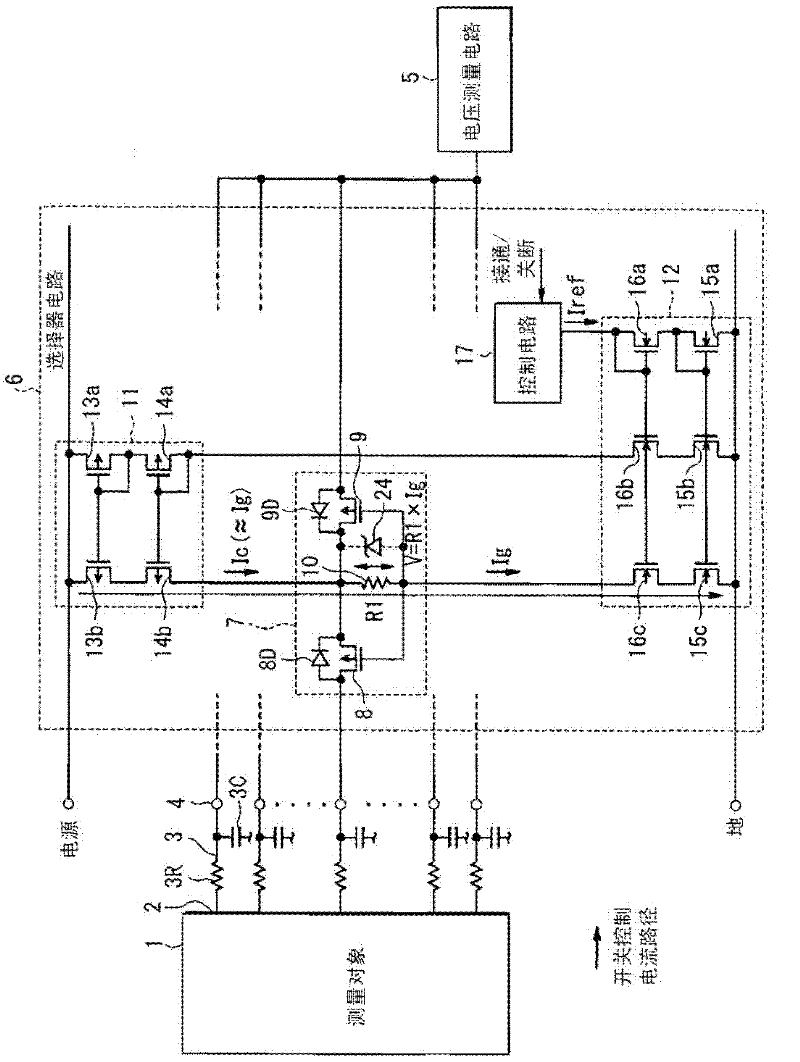
[0030] refer to figure 1 and figure 2 , shows a voltage measurement device that measures voltage (ie, potential) of a measurement object 1 , which may have a plurality of components. The measurement object 1 may be an assembled battery having a plurality of batteries coupled in series. In this assembled battery, there are a plurality of voltage measurement points 2 respectively having different voltages. Each voltage measurement point 2 is coupled to a measurement terminal 4 with a low-pass filter 3 . The low-pass filter 3 may include a resistor element 3R and a capacitor 3C. Furthermore, capacitor 3C may be coupled to a reference voltage suitable for forming a voltage measurement by using measurement terminal 4 .
[0031] The selector circuit 6 is coupled between the voltage measurement circuit 5 and the measurement terminal 4 corresponding to each of the plurality of voltage measurement points 2 . The selector circuit 6 comprises a plurality of switch circuits 7, where...
no. 2 example
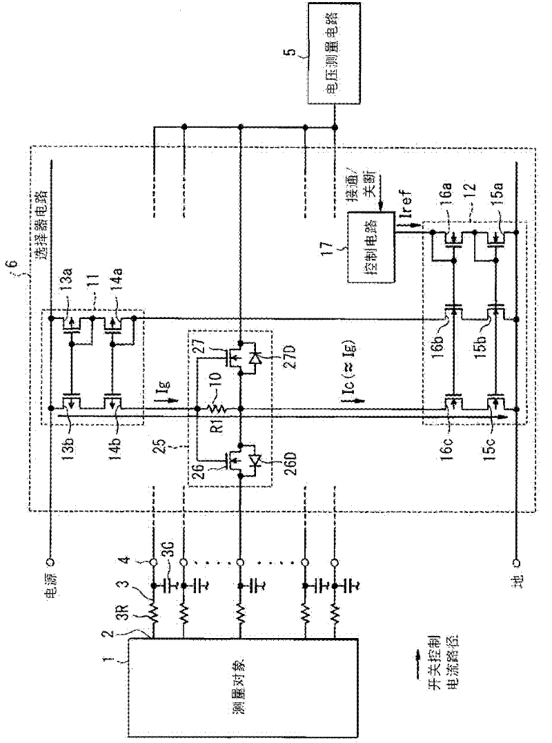
[0047] image 3 A second embodiment is shown in , in which parts similar to those of the first embodiment have similar reference numerals, and differences from the first embodiment are described below. In the second embodiment, a switch circuit 25 is used instead of the switch circuit 7 . The switch circuit 27 comprises two N-channel MOSFETs 26, 27 arranged with a common source connection and a common gate connection such that the N-channel MOSFETs 26, 27 distribution has parasitic diodes 26D, 27D arranged in opposite directions to each other. The gate of each of N-channel MOSFETs 26, 27 is coupled to the drain of P-channel MOSFET 14b, and the source of each of N-channel MOSFETs 26, 27 is coupled to the drain of N-channel MOSFET 16c .
[0048] In the above configuration, similar to the first embodiment, when the constant current Iref is supplied to the ground-side constant current circuit 12 through the control circuit 17, the mirror current Ic (≈Ig) flows to the resistor el...
no. 3 example
[0050] Figure 4 A third embodiment is shown in , in which parts similar to those of the first embodiment have similar reference numerals, and differences from the first embodiment are described below. In the third embodiment, the switch circuit 28 , the power-side constant current circuit 31 and the ground-side constant current circuit 32 replace the switch circuit 17 , the power-side constant current circuit 11 and the ground-side constant current circuit 12 , respectively.
[0051] The switch circuit 28 is configured to have two P-channel MOSFETs 8, 9 in the opposite connection direction to that of the first embodiment, so that the P-channel MOSFETs 8, 9 share a common drain. Furthermore, the parasitic diodes 8D, 9D have a common anode connection such that the diodes 8D, 9D are coupled to each other in opposite directions. The current carrying part of the switching circuit 28 is provided as two resistor elements 29 , 30 . Resistors 29 , 30 are coupled between the source a...
PUM
 Abstract
Description
Claims
Application Information