Ionized layer error estimation method and system for binary offset carrier (BOC) signal

An ionospheric error and offset carrier technology, applied in the field of navigation, can solve the problems of ionospheric delay estimation failure and high cost, and achieve the effect of small multipath effect and small measurement noise.

Active Publication Date: 2012-07-04
UNICORE COMM INC
View PDF3 Cites 8 Cited by
  • Summary
  • Abstract
  • Description
  • Claims
  • Application Information

AI Technical Summary

Problems solved by technology

However, the cost of multi-frequency receivers is significantly higher than that of single-frequency receivers, and the above methods are all based on the observations formed by signal t

Method used


Image

  • Ionized layer error estimation method and system for binary offset carrier (BOC) signal
  • Ionized layer error estimation method and system for binary offset carrier (BOC) signal
  • Ionized layer error estimation method and system for binary offset carrier (BOC) signal

Examples


Embodiment 1

[0105] Embodiment 1, a method for estimating an ionospheric error of a binary offset carrier signal, comprising:

[0106] Perform pseudorandom noise code, BOC subcarrier and carrier phase tracking on the intermediate frequency signal through the BOC signal tracking loop to obtain the first carrier phase;

[0107] tracking the upper sideband signal of the intermediate frequency signal to obtain a second carrier phase;

[0108] tracking the lower sideband signal of the intermediate frequency signal to obtain a third carrier phase;

[0109] According to the difference between the first carrier phase and the second carrier phase, and the difference between the first carrier phase and the third carrier phase, and the frequency of the center frequency of the BOC modulation signal, the upper sideband signal and the lower sideband signal, the total electron content TEC is obtained;

[0110] The error introduced by the ionospheric refraction in the carrier phase and pseudo-range obser...

Embodiment 2

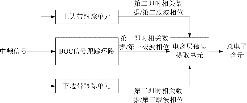
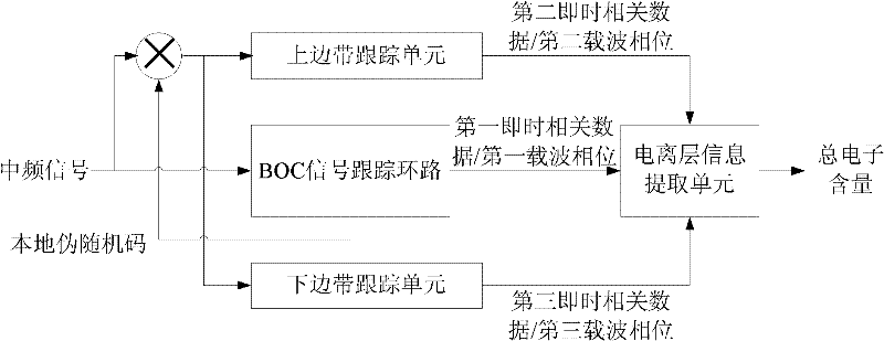
[0148] Embodiment 2, an ionospheric error estimation system of a binary offset carrier signal, comprising:

[0149] The BOC signal tracking loop is used for performing pseudo-random noise code, BOC subcarrier and carrier phase tracking on the intermediate frequency signal to obtain the first carrier phase;

[0150] an upper sideband tracking unit, configured to track the upper sideband signal of the intermediate frequency signal to obtain a second carrier phase;

[0151] A lower sideband tracking unit, configured to track the lower sideband signal of the intermediate frequency signal to obtain a third carrier phase;

[0152] The ionospheric information extraction unit is used for according to the difference between the first carrier phase and the second carrier phase, and the difference between the first carrier phase and the third carrier phase, and the center frequency of the BOC modulation signal, the frequency of the upper sideband signal and the lower sideband signal , t...


PUM


Abstract

The invention discloses an ionized layer error estimation method and an ionized layer error estimation system for a binary offset carrier (BOC) signal. The method comprises the following steps of: tracking pseudo-random noise codes, BOC subcarriers and carrier phases of an intermediate-frequency signal by using a BOC signal tracking ring to obtain a first carrier phase; tracking an upper sidebandsignal of the intermediate-frequency signal to obtain a second carrier phase; tracking a lower sideband signal of the intermediate-frequency signal to obtain a third carrier phase; obtaining a total electron content (TEC) according to the difference between the first carrier phase and the second carrier phase, difference between the first carrier phase and the third carrier phase, the center frequency of a BOC modulating signal, and frequencies of the upper sideband signal and the lower sideband signal; and calculating errors introduced by ionospheric refraction to the carrier phase and pseudorange observation quantity according to the TEC. The BOC signal can be subjected to signal-frequency ionized layer error estimation; and the TEC is calculated by the carrier phases, so the method andthe system are slightly influenced by a multi-path effect and measurement noise.

Description

technical field [0001] The invention relates to the field of navigation, in particular to an ionospheric error estimation method and system for a binary offset carrier signal. Background technique [0002] The speed at which waves propagate in a medium depends on the refractive index of the medium. The refractive index n is defined as the ratio of the electromagnetic wave propagation speed c in free space to the speed v in the medium. For the electromagnetic wave emitted by GNSS (Global Navigation Satellite System, Global Navigation Satellite System), it propagates at the speed of light in free space, and the propagation speed in the ionosphere and troposphere is not equal to the speed of light. [0003] Refractive index: n=c / v(1) [0004] A medium is dispersive for a wave if the refractive index of the wave in the medium is not constant but is a function of the frequency f. For L-band electromagnetic waves, the ionosphere is a dispersive medium, and the troposphere is a ...

Claims


Application Information

Patent Timeline
IPC IPC(8): G01S19/29G01S19/21
Inventor 莫钧韩绍伟邱剑宁
Owner UNICORE COMM INC
Why Eureka
Try Eureka