Microwave measurement device, system and method
A technology of microwave measurement, main device, applied in the direction of measurement device, radio wave measurement system, reflection/re-radiation of radio waves, etc.
- Summary
- Abstract
- Description
- Claims
- Application Information
AI Technical Summary
Problems solved by technology
Method used
Image
Examples
Embodiment 1
[0064] This embodiment provides a microwave measuring device, system and method, wherein the microwave measuring device includes a signal transmitting part, a signal receiving part, a digital signal processor and a controller; wherein:
[0065] The signal transmitting part is used to generate N-channel transmission signals, and synthesize the power of N-channel transmission signals into one signal before transmitting; N is a positive integer not less than 2, and the frequencies of N-channel transmission signals are different, and two adjacent transmission channels The frequency interval of the signal is not less than 20% of the frequency of the transmission signal with the smaller frequency value in the two signals; the aforementioned two adjacent transmission signals refer to the two adjacent signals sorted according to the signal frequency, that is, the frequency Two-way signals that are close.
[0066] The signal receiving part is used to receive the radio frequency signal ...
Embodiment 2
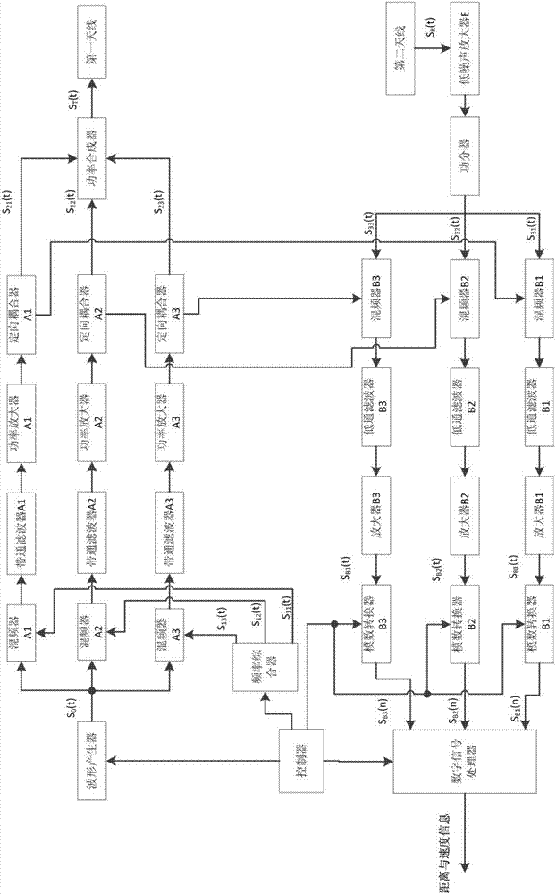
[0101] In this embodiment, a microwave measurement device in which the value of N is 3 is provided. Such as figure 1 As shown, the microwave measuring device includes a signal transmitting part, a signal receiving part, a digital signal processor and a controller.
[0102] The main function of the signal transmitting part is to generate 3 transmission signals, and combine the power of the 3 transmission signals into one signal before transmitting. The signal transmitting part includes: waveform generator, frequency synthesizer, mixer A1, mixer A2, mixer A3, band-pass filter A1, band-pass filter A2, band-pass filter A3, power amplifier A1, Power amplifier A2, power amplifier A3, directional coupler A1, directional coupler A2, directional coupler A3, power combiner and first antenna, wherein the polarization mode of the first antenna is X polarization, in this embodiment, X The polarization is horizontal.
[0103] Band-pass filter A1, power amplifier A1 and directional coupler ...
Embodiment 3
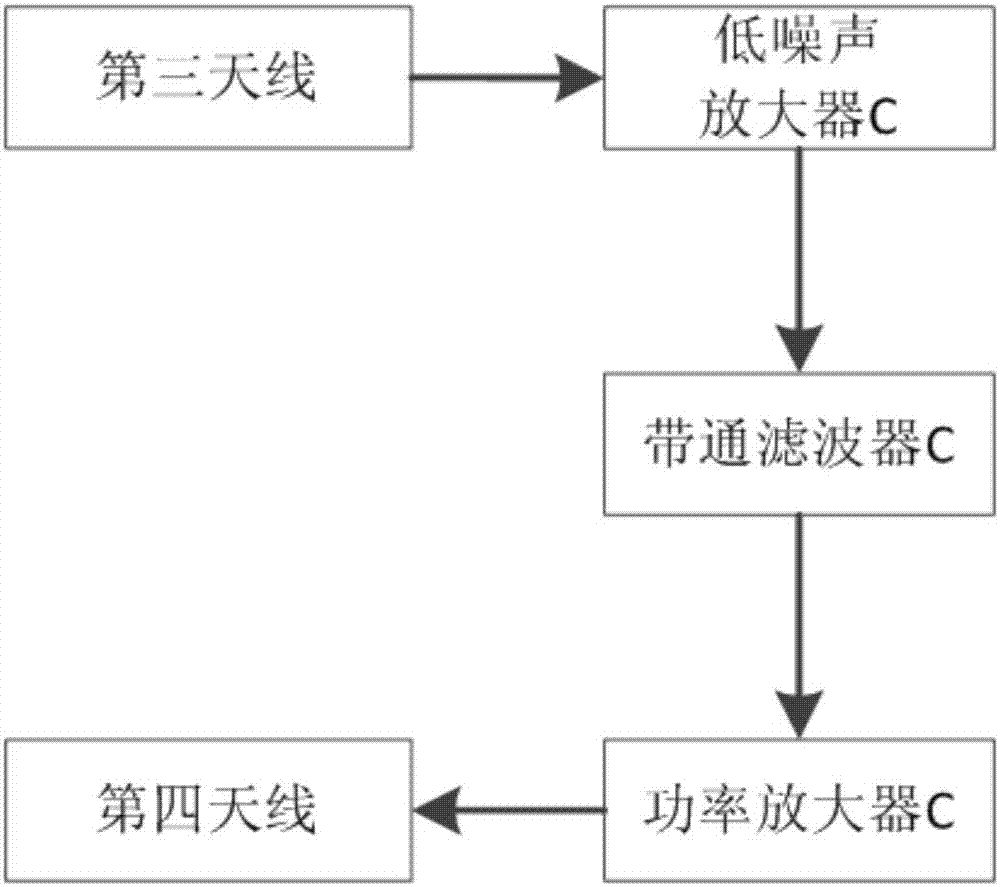
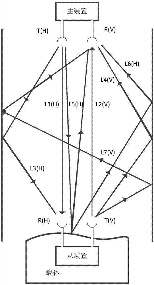
[0113] This embodiment provides a microwave measurement system, which includes a master device and a slave device. The master device in this embodiment adopts the microwave measurement device in Embodiment 2, and the slave device adopts a same-frequency transponder. In this embodiment, the The structure of the same frequency transponder as figure 2 shown.
[0114] The slave device includes a third antenna, a fourth antenna, a low noise amplifier C, a bandpass filter C and a power amplifier C. Wherein, the polarization mode of the third antenna is the same as that of the first antenna, which is X polarization; the polarization mode of the fourth antenna is the same as that of the second antenna, which is Y polarization, and the polarization mode of the third antenna and the fourth antenna is positive intersection; the beams of the first antenna and the second antenna have the same direction; the beams of the third antenna and the fourth antenna have the same direction and are...
PUM
 Abstract
Description
Claims
Application Information
 - R&D
- Intellectual Property
- Life Sciences
- Materials
- Tech Scout
- Unparalleled Data Quality
- Higher Quality Content
- 60% Fewer Hallucinations
Browse by: Latest US Patents, China's latest patents, Technical Efficacy Thesaurus, Application Domain, Technology Topic, Popular Technical Reports.
© 2025 PatSnap. All rights reserved.Legal|Privacy policy|Modern Slavery Act Transparency Statement|Sitemap|About US| Contact US: help@patsnap.com


