
Indoor positioning method and device based on visible light, electronic equipment and storage medium

An indoor positioning and visible light technology, which is applied in positioning, measuring devices, and photo interpretation, can solve the problems of positioning blind spots, high deployment costs, low positioning accuracy and reliability, and achieve the effect of reducing hardware costs and high positioning accuracy

Pending Publication Date: 2019-12-06
CHINA ACADEMY OF ELECTRONICS & INFORMATION TECH OF CETC
View PDF0 Cites 0 Cited by
  • Summary
  • Abstract
  • Description
  • Claims
  • Application Information

AI Technical Summary

Problems solved by technology

However, in indoor or underground environments, due to attenuation or occlusion of satellite signals, positioning services are no longer effective, forming a positioning blind zone
[0004] In response to this problem, indoor positioning methods based on the principles of Wi-Fi (Wireless Fidelity), Bluetooth, ultrasound, infrared, ultra-wideband, computer vision, and laser radar have gradually emerged. Problems of high cost, low positioning accuracy and reliability

Method used


Image

  • Indoor positioning method and device based on visible light, electronic equipment and storage medium
  • Indoor positioning method and device based on visible light, electronic equipment and storage medium
  • Indoor positioning method and device based on visible light, electronic equipment and storage medium

Examples


Embodiment Construction

[0064] In order to further explain the technical means and functions adopted by the present invention to achieve the intended purpose, the present invention will be described in detail below in conjunction with the accompanying drawings and preferred embodiments.

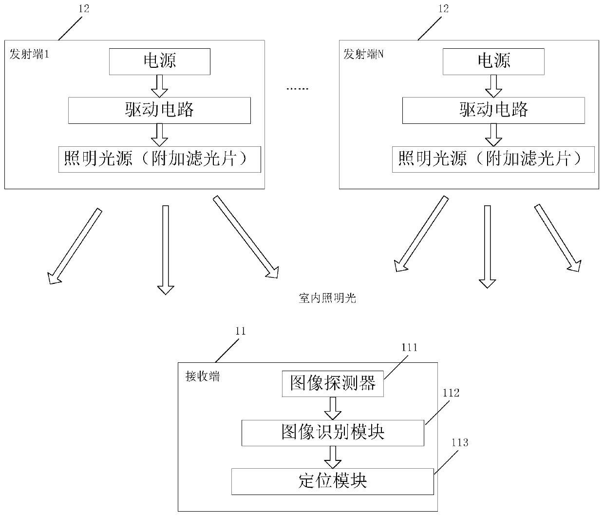
[0065] The basic principle of indoor visible light positioning technology is to use the existing indoor lighting source as a positioning light beacon, and at the same time use the mobile terminal to receive the optical signal from the light source to complete the positioning. Compared with other positioning technologies, visible light positioning technology can use lighting sources to simultaneously complete lighting and positioning functions, so it has the advantages of low cost, low energy consumption, no electromagnetic interference, and no need for spectrum authorization. In addition, compared with radio frequency signals, visible light signals have shorter wavelengths, so they are less affected by multipath effe...


PUM


Abstract

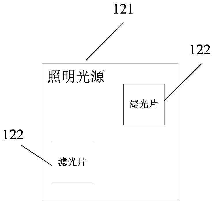
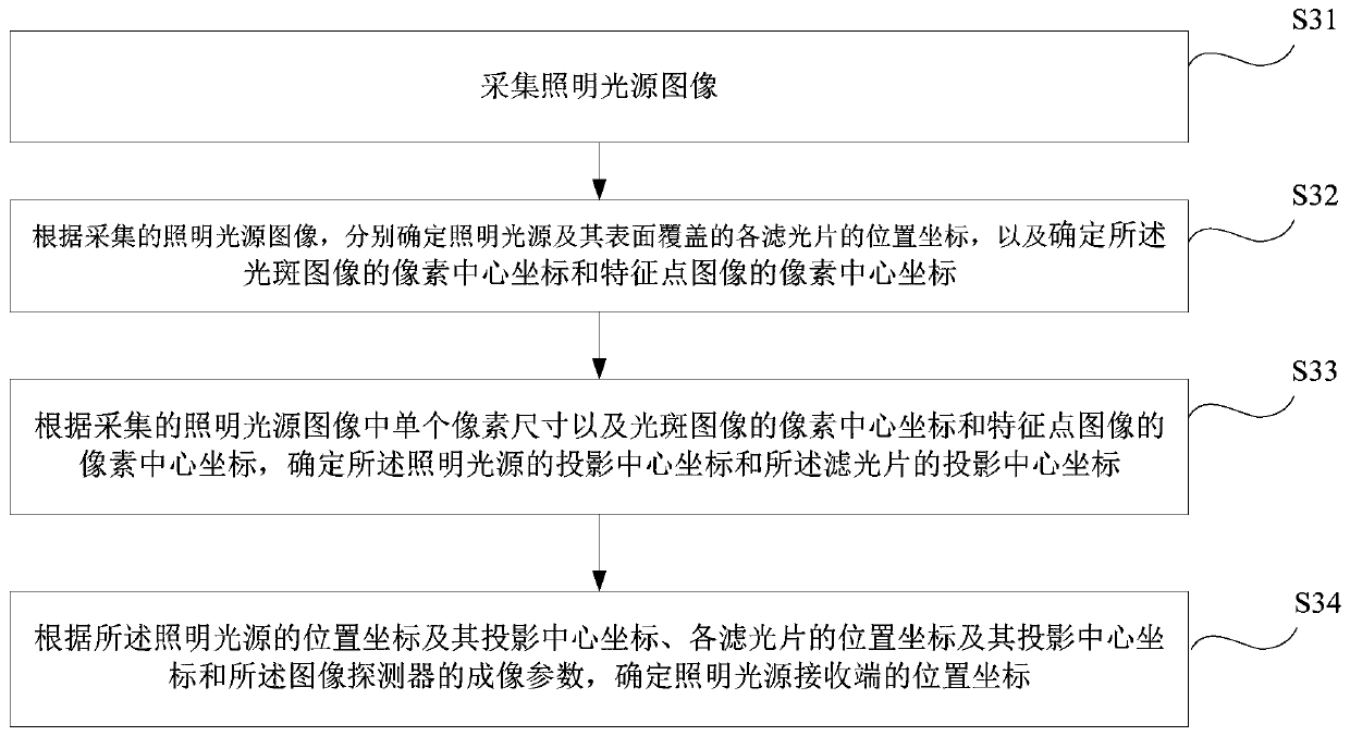
The invention provides an indoor positioning method and device based on visible light, electronic equipment and a storage medium, which are used for improving positioning precision and reliability ofthe positioning method and reducing hardware cost of indoor positioning. The method comprises the steps: collecting lighting source images, wherein a part of surface of a lighting source is covered with a plurality of optical filters, and the lighting source images comprise a light spot image and a feature point image; according to the collected lighting source images, determining position coordinates of the lighting source and each optical filter covered on the surface of the lighting source, and determining a pixel center coordinate of the light spot image and the feature point image; determining a projection center coordinate of the lighting source and the optical filters according to single pixel size in the collected lighting source images and the pixel center coordinate of the lightspot image and the feature point image; and determining a position coordinate of the receiving end of the lighting source according to the position coordinate and the projection center coordinate of the lighting source, the position coordinates and the projection center coordinates of the optical filters and imaging parameters of an image detector.

Description

technical field [0001] The present invention relates to the technical field of indoor positioning, in particular to an indoor positioning method, device, electronic equipment and storage medium based on visible light. Background technique [0002] With the development of smart mobile terminals and Internet of Things technology, applications based on indoor location continue to emerge. Whether it is in the field of public services, commercial activities or industrial production, location information is one of the important basic information and plays an important role. [0003] At present, global positioning systems based on satellite signals (such as GPS, Beidou, etc.) have been popularized and have a very wide range of applications. However, in indoor or underground environments, due to attenuation or occlusion of satellite signals, positioning services are no longer effective, forming a positioning blind zone. [0004] In response to this problem, indoor positioning meth...

Claims


Application Information

Patent Timeline
Patent Type & Authority Applications(China)
IPC IPC(8): G01C21/20G01C11/04G01S5/16G01C11/30
CPCG01C21/206G01C11/04G01S5/16G01C11/30
Inventor 蔺博黄河清
Owner CHINA ACADEMY OF ELECTRONICS & INFORMATION TECH OF CETC
Learn More