Microwave measuring device, system and method

A technology of microwave measurement, main device, applied in the direction of measurement device, radio wave measurement system, reflection/re-radiation of radio waves, etc.

Active Publication Date: 2020-01-21
CHENGDU ZERO TECH
View PDF8 Cites 0 Cited by
  • Summary
  • Abstract
  • Description
  • Claims
  • Application Information

AI Technical Summary

Problems solved by technology

[0007] The object of the present invention is to provide a microwave measurement system to solve the problem of distance and / or speed measurement in a closed electromagnetic propagation environment

Method used


Image

  • Microwave measuring device, system and method
  • Microwave measuring device, system and method
  • Microwave measuring device, system and method

Examples


Embodiment 1

[0064] This embodiment provides a microwave measuring device, system and method, wherein the microwave measuring device includes a signal transmitting part, a signal receiving part, a digital signal processor and a controller; wherein:

[0065] The signal transmitting part is used to generate N-channel transmission signals, and synthesize the power of N-channel transmission signals into one signal before transmitting; N is a positive integer not less than 2, and the frequencies of N-channel transmission signals are different, and two adjacent transmission channels The frequency interval of the signal is not less than 20% of the frequency of the transmission signal with the smaller frequency value in the two signals; the aforementioned two adjacent transmission signals refer to the two adjacent signals sorted according to the signal frequency, that is, the frequency Two-way signals that are close.

[0066] The signal receiving part is used to receive the radio frequency signal ...

Embodiment 2

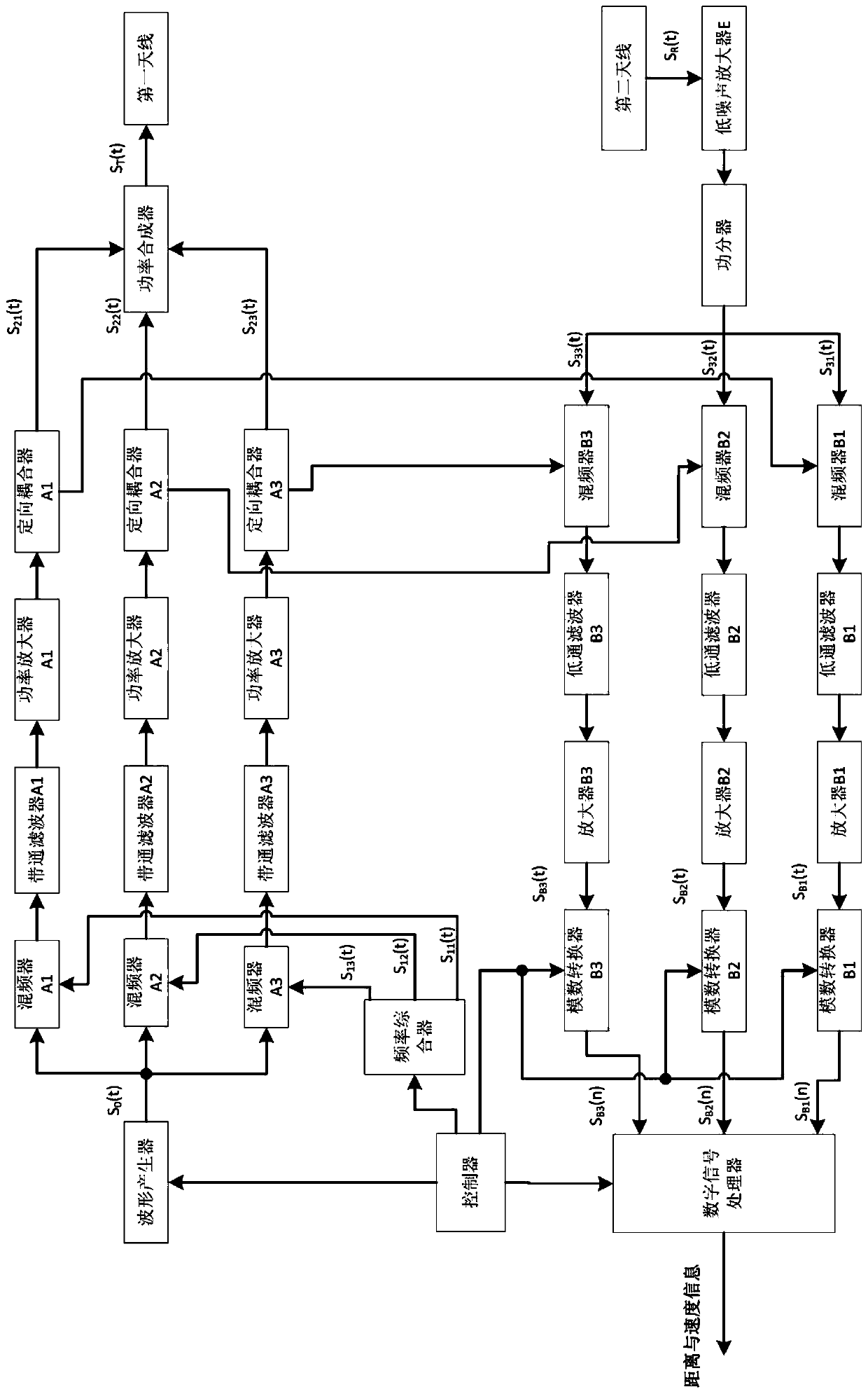
[0101] In this embodiment, a microwave measurement device in which the value of N is 3 is provided. Such as figure 1 As shown, the microwave measuring device includes a signal transmitting part, a signal receiving part, a digital signal processor and a controller.

[0102] The main function of the signal transmitting part is to generate 3 transmission signals, and combine the power of the 3 transmission signals into one signal before transmitting. The signal transmitting part includes: waveform generator, frequency synthesizer, mixer A1, mixer A2, mixer A3, band-pass filter A1, band-pass filter A2, band-pass filter A3, power amplifier A1, Power amplifier A2, power amplifier A3, directional coupler A1, directional coupler A2, directional coupler A3, power combiner and first antenna, wherein the polarization mode of the first antenna is X polarization, in this embodiment, X The polarization is horizontal.

[0103] Band-pass filter A1, power amplifier A1 and directional coupler ...

Embodiment 3

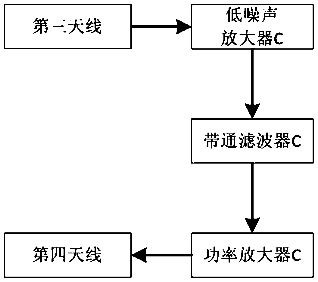
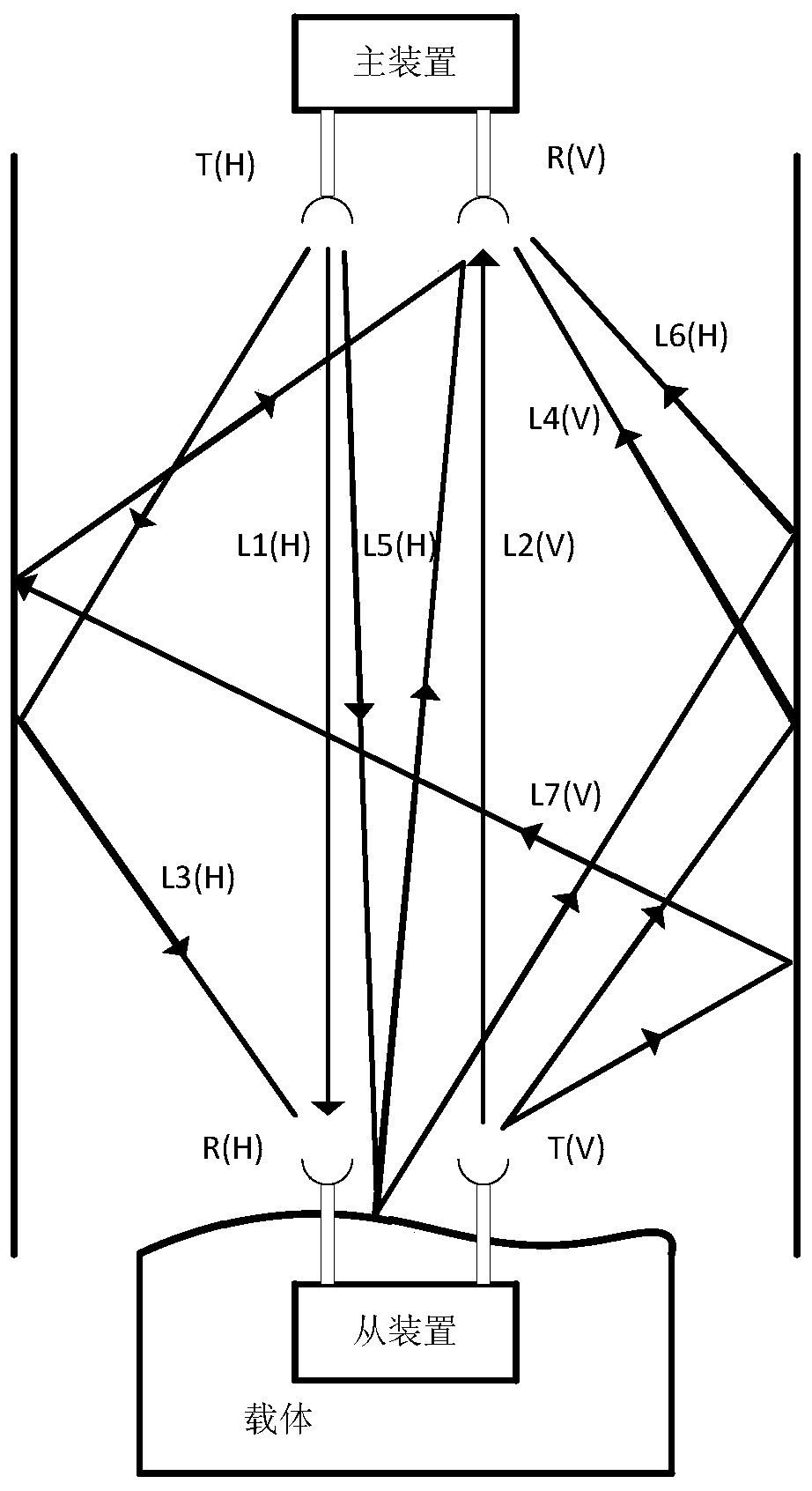
[0113] This embodiment provides a microwave measurement system, which includes a master device and a slave device. The master device in this embodiment adopts the microwave measurement device in Embodiment 2, and the slave device adopts a same-frequency transponder. In this embodiment, the The structure of the same frequency transponder as figure 2 shown.

[0114] The slave device includes a third antenna, a fourth antenna, a low noise amplifier C, a bandpass filter C and a power amplifier C. Wherein, the polarization mode of the third antenna is the same as that of the first antenna, which is X polarization; the polarization mode of the fourth antenna is the same as that of the second antenna, which is Y polarization, and the polarization mode of the third antenna and the fourth antenna is positive intersection; the beams of the first antenna and the second antenna have the same direction; the beams of the third antenna and the fourth antenna have the same direction and are...


PUM


Abstract

The invention discloses a microwave measurement device, system and method. The system comprises a master device and a slave device; the master device comprises a signal transmitting part, a signal receiving part, a digital signal processor and a controller; the signal transmitting part comprises a first antenna, the signal transmitting part is used for generating N paths of transmitting signals, and, after the N paths of the transmitting signals are converted into one path of a signal through power synthesis, the signal transmitting part is used for transmitting the one path of the signal via the first antenna; the signal receiving part comprises a second antenna, the first antenna and the second antenna are in orthogonal polarization, the signal receiving part is used for receiving a radio-frequency signal forwarding by the slave device, the radio-frequency signal is divided into N paths and then are respectively processed to be N paths of digital signals, and the N paths of the digital signals are sent to a digital signal processor; the digital signal processor calculates a distance and / or a speed of a measurement object according to the received N paths of the digital signal; and the slave device receives the transmitting signal of the master device and forwards the transmitting signal of the master device in same frequency. The device, system and method have capabilities of preventing transmitting multipath, clutter multipath, other primary multipath and corresponding multi-time multipath; and distance and / or speed measurements of a moving vehicle and other objects can be achieved in an enclosed electromagnetic transmission environment.

Description

technical field [0001] The invention relates to a measurement technology for distance and speed measurement by using microwaves, in particular to a microwave measurement device, system and method. Background technique [0002] Distance and / or speed measurement technology is a basic measurement technology. Compared with other distance measurement technologies such as image ranging and speed measurement, ultrasonic distance measurement and speed measurement, it has the advantages of all-day, all-weather, and long-distance, and is widely used in various distances and / or speed monitoring application scenarios. [0003] In practical applications, microwave distance or velocity measurement techniques will be affected by multipath effects, resulting in limited use. The multipath effect means that after the electromagnetic wave propagates through different paths, each component field arrives at the receiving end at different times, and their phases are superimposed on each other to...

Claims


Application Information

Patent Timeline
Patent Type & Authority Patents(China)
IPC IPC(8): G01S13/32G01S13/58
CPCG01S13/32G01S13/584
Inventor 陈祝明
Owner CHENGDU ZERO TECH
Why Eureka
Try Eureka