Automatic calibration device and method for abbe cosine error of interferometer

An automatic calibration and interferometer technology, which is applied in the exposure device, instrument, optics and other directions of the photoplate making process, can solve the problems of non-coincidence of beam measurement directions, cosine error, cumbersomeness, etc., and achieve the effect of solving calibration problems

Active Publication Date: 2012-07-04
SHANGHAI MICRO ELECTRONICS EQUIP (GRP) CO LTD
View PDF6 Cites 9 Cited by
  • Summary
  • Abstract
  • Description
  • Claims
  • Application Information

AI Technical Summary

Problems solved by technology

[0005] 2. The motion direction of the moving table does not coincide with the beam measurement direction, thus introducing a cosine error, such as figure 2
[0010] 1) It needs to go through at least 4 steps: exposure, development, graphic reading, and model calculation, which are relatively cumbersome;
[0011] 2) When the vertical direction of the motion table is also controlled by an interferometer, this method cannot calibrate the Abbe arm and cosine angle of the vertical measurement interferometer

Method used


Image

  • Automatic calibration device and method for abbe cosine error of interferometer
  • Automatic calibration device and method for abbe cosine error of interferometer
  • Automatic calibration device and method for abbe cosine error of interferometer

Examples


no. 1 example

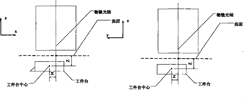
[0071] Such as image 3 As shown, the position X of the workpiece table of the lithography machine is defined as: the x-direction distance between the center of the workpiece table and the intersection point between the optical axis of the objective lens and the focal plane; the position Y of the workpiece table is defined as: the distance between the center of the workpiece table and the intersection point between the optical axis of the objective lens and the focal plane The distance in the y direction; the position Z of the workpiece table is defined as: the distance from the focal plane to the center of the workpiece table. When the workpiece table is rotated (Rz) or tilted (Rx, Ry), it is carried out around the intersection of the optical axis of the objective lens and the focal plane, and the counterclockwise direction is positive, and the clockwise direction is negative.

[0072] Figure 4 The X, Y, and Z positions of the workpiece table can be measured by the lithogra...

no. 2 example

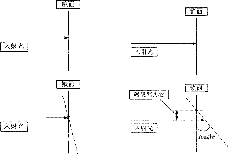
[0096] In addition to the Abbe cosine error in the first embodiment of the workpiece stage interferometer system, the distance Dx and Dy of the two interfering beams (as shown in Error! Reference source not found.) is not calibrated, and an Abbe arm will also be generated , making the measured rotation inaccurate.

[0097] The second embodiment is similar to the above-mentioned first embodiment, the difference is that this second embodiment uses one more object plane mark on the basis of the above-mentioned first embodiment. In addition to the Abbe arm and cosine angle, another Abbe arm Dx, Dy can be additionally measured, that is, the distance between the two beams. The method is as follows:

[0098] There are two marks with the same y value on the object surface, move the mask table so that it is within the field of view, move the workpiece table to a set position (nominal position), and at the set position, the work table is on the The aerial image sensor can detect the a...

no. 3 example

[0113] The method for automatic calibration of the Abbe cosine error of the interferometer described in the present invention can also be applied to the calibration of the mask table interferometer.

[0114] Such as Figure 11 Shown is the mask stage position definition. The mask table position X is defined as: the x-direction distance from the center of the mask table to the intersection of the optical axis of the objective lens and the focal plane; the mask table position Y is defined as: the y-direction from the center of the mask table to the intersection of the optical axis of the objective lens and the focal plane Distance; the mask table position Z is defined as: the distance from the object plane to the center of the mask plane. When the mask table is rotated (Rz) or tilted (Rx, Ry), it is carried out around the intersection point of the optical axis of the objective lens and the object plane, and the counterclockwise direction is positive, and the clockwise direction...


PUM


Abstract

The invention discloses an automatic calibration device for abbe cosine error of an interferometer of a lithography machine. The device comprises an illuminating light source, a mask table, an objective imaging system, a workpiece table and an interferometer, wherein the illuminating light source is provided with an object plane mark; the interferometer is arranged on the workpiece table; the device is characterized by also comprising a space image sensor which is arranged on the workpiece table; and by differently rotating and tilting the workpiece table, a measurement result of the interferometer can be compared with a normal position of the workpiece or the theoretical position of an object plane mark space image by the space image sensor when the object plane mark space image is detected by the space image sensor, and fitting is performed to obtain abbe arm and cosine angle of the workpiece table interferometer. The invention also provides an automatic calibration device for the abbe cosine error of the interferometer of the lithography machine. Mark measurement is performed by using the space image sensor, so that the abbe arm and the cosine angle of the interferometer are calibrated without exposure or development. Meanwhile, the problem of calibration of a vertical interferometer can also be solved.

Description

technical field [0001] The invention relates to the technical field of semiconductor manufacturing, in particular to an automatic calibration device and method for the Abbe cosine error of a lithography machine interferometer. Background technique [0002] During the scanning lithography exposure process, the mask stage and the worktable need to perform relative movement for scanning. In order to make the pattern on the reticle imaged on the corresponding position on the silicon wafer with good imaging quality, it is necessary to obtain real-time images of the workpiece stage / mask stage in the horizontal direction (X direction) and horizontal longitudinal direction (Y direction) during the exposure process. ), the rotation Rz around the vertical direction (Z direction), the vertical direction (Z direction), the tilt Rx around the horizontal direction (X direction), and the position information on the six degrees of freedom around the horizontal longitudinal (Y direction) til...

Claims


Application Information

Patent Timeline
Patent Type & Authority Applications(China)
IPC IPC(8): G03F9/00G03F7/20
Inventor 许琦欣孙刚
Owner SHANGHAI MICRO ELECTRONICS EQUIP (GRP) CO LTD
Why Eureka
Try Eureka