Multi-screen parallel massive information display system

A mass information and display system technology, applied in the direction of concurrent instruction execution, machine execution device, digital output to display equipment, etc., can solve poor scalability, does not support arbitrary combination of input and output images, arbitrary partition, weak matrix switching function, etc. problem, to achieve the effect of increased signal processing capability, easier maintenance and upgrade, and realization of multi-machine redundancy

Inactive Publication Date: 2012-07-04
GUANGZHOU HANYANG INFORMATION TECH
View PDF3 Cites 28 Cited by
  • Summary
  • Abstract
  • Description
  • Claims
  • Application Information

AI Technical Summary

Problems solved by technology

[0005] (1) It is unable to process and display the user's large amount of data information, and at the same time, it cannot be compatible with new image input methods on the market;
[0006] (2) The system function combination, display, partition, and image exchange capabilities are relatively poor, and the input and output image matrix exchange capabilities between the same video controller are relatively good. When multiple video controllers are configured with a large number of screens, the two The matrix switching function between the input and output images of different video controllers is relatively weak; the general functional partition is based on the video controller, and basically does not support any combination or partition of input and output images between different controllers;
[0007] (3) The stability and reliability of the system are not high. At present, the video controllers of mainstream manufacturers are still based on industrial computers, so it is a severe test for the stability and reliability of the sy

Method used


Image

  • Multi-screen parallel massive information display system
  • Multi-screen parallel massive information display system
  • Multi-screen parallel massive information display system

Examples


example

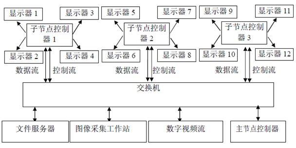
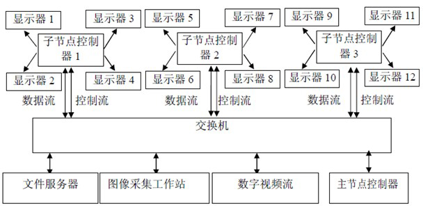
[0076] Take the common 3 rows and 4 columns splicing display wall as an example for the system splicing principle as attached figure 1 As shown, the system forms an overall local area network through switches. The Head node master node controller and multiple Rendering Node sub-node controllers are connected to the LAN through the switch interface. The image acquisition modules in different formats are also connected to the local area network through the switch interface. The digital video stream signal or file server can directly enter the network through the switch interface, and the analog video stream signal can pass through the image acquisition workstation (that is, the signal conversion unit) and then enter the local area network through the switch interface.

[0077] The processing flow of the video signal is: the digital video stream directly entering the network or the analog video stream input through the image acquisition workstation is sent to each sub-node cont...


PUM


Abstract

The invention provides a multi-screen parallel massive information display system. An integral splicing wall is divided by the system with four screens as a unit, each four screens are controlled by an accessory node controller, and the accessory node controllers are connected with a master node controller through a high-speed internet. Under unified allocation and organization of the master node controller, external massive data (including analog video signals, digital signals of a computer and the like) are transmitted to the high-speed internet after quantization and digital processing and finally transmitted to the accessory node controllers, and images are parallelly rendered to a video memory by the accessory node controllers and displayed on a high-definition splicing display screen. The system comprehensively applies the CPU (central processing unit)+CPU parallel processing technology, the cloud computing technology and the high-speed network technology, so that the massive data which cannot be processed and displayed by a traditional system are quickly displayed in real time.

Description

Technical field [0001] The invention involves communication and computer fields, especially a multi -screen parallel mass information display system. Background technique [0002] At present, the mainstream information display system of the market uses a centralized control computing method to control the display unit. With the continuous development of technology and the user's requirements for product performance and display effects, it continues to improve. [0003] The existing information display system uses a centralized control computing method to control the display unit.That is, all input images must be connected to the video controller, and all output images are output by the video controller.The core components of this processing method are image spiers. Most of the equipment is designed with pure hardware structure and no operating system.The decoding and rendering work of the entire large -screen display image is concentrated in the image splicter. The system has poo...

Claims


Application Information

Patent Timeline
IPC IPC(8): G06F3/14G06F9/38
Inventor 孙峻岭
Owner GUANGZHOU HANYANG INFORMATION TECH
Why Eureka
Try Eureka