High-impedance combined-type transformer

A combined transformer and transformer technology, applied in the direction of transformers, fixed transformers, transformer/inductor coils/windings/connections, etc., can solve the problems affecting the development of the power industry, difficult to transport to substations, complex insulation structures, etc. The effect of low difficulty, simple disassembly, and easy transportation

Active Publication Date: 2012-07-04
TBEA HENGYANG TRANSFORMERS
View PDF5 Cites 6 Cited by
  • Summary
  • Abstract
  • Description
  • Claims
  • Application Information

AI Technical Summary

Problems solved by technology

These methods have disadvantages such as complex insulation structure and high cost to varying degrees.
[0004] In addition, for large-scale transformers with large volume and

Method used


Image

  • High-impedance combined-type transformer
  • High-impedance combined-type transformer
  • High-impedance combined-type transformer

Examples


Embodiment Construction

[0021] In order to enable those skilled in the art to better understand the technical solutions of the present invention, the high impedance combined transformer of the present invention will be described in further detail below in conjunction with the accompanying drawings and specific embodiments.

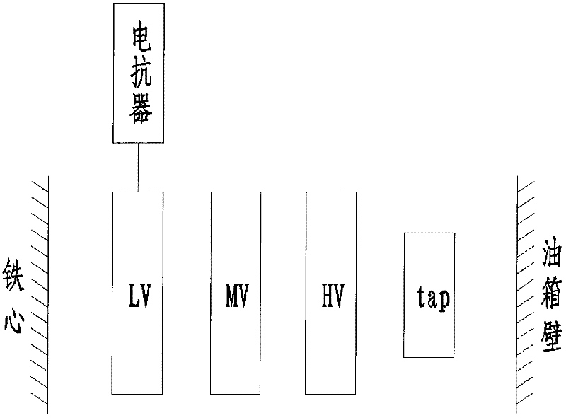
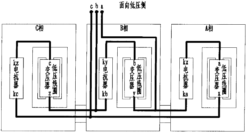
[0022] Such as image 3 As shown, in this embodiment, the high impedance combined transformer includes three single-phase transformers and three transformer tanks. The three single-phase transformers are respectively placed in three transformer tanks, and the three single-phase transformers are combined to form one Three-phase transformer. Wherein, the body structures of the three single-phase transformers are the same, and the oil tanks of the three transformers are connected to each other through corrugated pipes, so that the oil circuits in the oil tanks of the three transformers are connected.

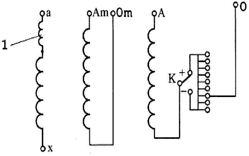
[0023] Such as figure 1 As shown, in the three-phase transformer, each phase transfor...


PUM


Abstract

The invention provides a high-impedance combined-type transformer which comprises three single-phase transformers and three transformer oil tanks, wherein the three single-phase transformers are respectively arranged in the three transformer oil tanks; the three single-phase transformers are combined to form a three-phase transformer; in the three-phase transformer, each phase of transformer comprises a low-voltage winding, a medium-voltage winding and a high-voltage winding; a reactor is arranged in each transformer oil tank; and the low-voltage winding of each phase of transformer is connected in series with the reactor of the transformer oil tank where the phase transformer is positioned. The high-impedance combined-type transformer can be in high-impedance operation and in split-type transportation, and has high performance-price ratio.

Description

Technical field [0001] The invention belongs to the technical field of power transformers, and specifically relates to a high-impedance combined transformer. Background technique [0002] With the development of my country's power industry, product reliability is becoming more and more important. High-impedance transformers are widely used due to their many advantages, such as: their large impedance can effectively reduce the short-circuit current of the system, improve the short-circuit resistance of the product, and ensure product reliability. Moreover, based on the above advantages, the cost of system protection facilities can be reduced, which can greatly reduce the construction cost of power stations. Therefore, more and more substations tend to use high impedance transformers. [0003] At present, the common methods for high impedance transformers to achieve high impedance are: a. High voltage built-in; b. Split winding; c. Add medium and low voltage coils. These methods ha...

Claims


Application Information

Patent Timeline
IPC IPC(8): H01F30/12H01F27/28H01F27/40
Inventor 贾贺强何海江熊峰宁朝晖
Owner TBEA HENGYANG TRANSFORMERS
Why Eureka
Try Eureka