
Electrical motor for mixed power vehicles

A technology for hybrid electric vehicles and motor housings, which is applied in the manufacture of motor generators, electric components, electrical components, etc., and can solve the problems of reducing motor torque density, low cooling efficiency of rotors, and reducing motor circumferential force torque, etc.

Inactive Publication Date: 2006-07-19
CHERY AUTOMOBILE CO LTD
View PDF0 Cites 8 Cited by
  • Summary
  • Abstract
  • Description
  • Claims
  • Application Information

AI Technical Summary

Problems solved by technology

However, there are certain contradictions in its structure: 1. Since the structure of the stator coil requires a large space, the radius of the excitation position of the armature and the rotor magnet is greatly reduced under the same external dimensions, and the torque of the circumferential force of the motor is reduced; thus The torque density of the motor is reduced; 2. In order to increase the torque density, the torque needs to be increased, so the diameter of the rotor has to be increased, thereby increasing the diameter of the motor; 3. The installation of the magnet is difficult to fix due to the centrifugal force. Winding is required; 4. The efficiency of rotor cooling is not high
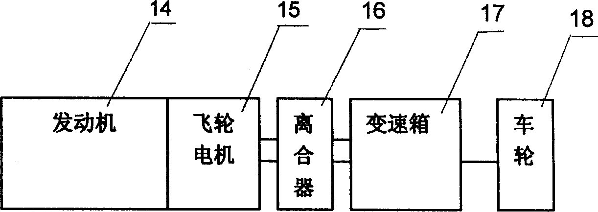
[0003] like image 3 As shown, the motor is used in a coaxial hybrid vehicle. Since the motor is coaxial with the engine crankshaft, the rotor of the motor is fixed with the flywheel of the engine, which further highlights the above-mentioned defects, so the moment of inertia at the output end of the engine will be increased, and Due to the structure of the motor, the length of the powertrain will be increased, making it difficult to arrange the front cabin

Method used


Image

  • Electrical motor for mixed power vehicles
  • Electrical motor for mixed power vehicles
  • Electrical motor for mixed power vehicles

Examples


Embodiment Construction

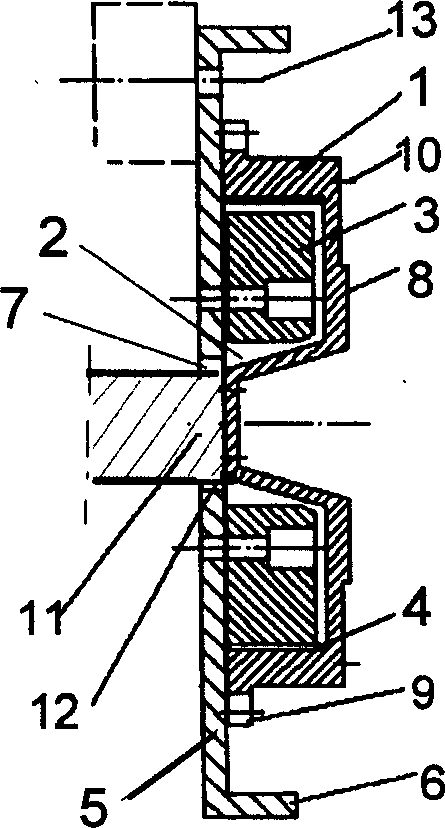
[0017] Such as figure 1 , figure 2 As shown, a motor for a hybrid electric vehicle includes a rotor 1 composed of a permanent magnet 4 and an iron core, and a stator 3 whose coils are Y-connected and connected to an inverter circuit. The rotor 1 has an E-shaped radial section, and the stator 3 is placed in the annular groove 2 of the rotor 1 , and a motor housing 5 connected with the rotor 1 is provided on one side of the notch of the rotor annular groove 2 . The motor housing 5 has a circular cylindrical body 6 protruding from the rotor 1 side along its radial end face, and a perforation 7 passing through the engine crankshaft 11 is provided at the axial position of the motor housing 5 . The engine crankshaft 11 is coupled to the rotor end face 12 via the bore 7 . The axial outer side of the ring groove 2 of the rotor 1 is provided with a friction surface 8, which is connected according to the structural type of the clutch, and its radial outer side is provided with a rin...


PUM


Abstract

The invention relates to a motor used in the mixed power vehicle, which comprises a rotor and a stator formed by permanent magnet and iron core. Wherein, the radial section of said rotor is in E-shape; the stator is inside the rotor annular groove whose part at one side of rotor annular groove has a motor case connecting the stator. The permanent magnet is circumferentially arranged at the inner surface of rotor, and with the increase of inner surface radius and in same motor size, since the torque of circumferential magnetic field sensing force is increased, the torque density of motor is improved significantly; the flywheel of motor is integrated with the rotor of electric motor; the rotary inertia of rotor is increased significantly; therefore, it can reduce the number of flywheels on the traditional power integration to integrate the motor and flywheels, with small volume, reduced weight of power integration, axial length, lower short-circuit current and lower instant brake torque.

Description

technical field [0001] The invention relates to a motor, in particular to a motor for a hybrid vehicle. Background technique [0002] A traditional motor consists of rotor coils and stator armature coils. A permanent magnet brushless motor consists of a rotor with permanent magnets and a stator field coil. The structural form of the permanent magnet motor and the traditional motor form both appear in the structural form of an inner rotor. The stator is structurally located on the outer ring of the rotor, and the permanent magnets on the rotor are fixed on the outer circumference of the rotor; this structural form Relatively reliable, excellent performance, high power density, simple structure, stable and reliable performance and so on. However, there are certain contradictions in its structure: 1. Since the structure of the stator coil requires a large space, the radius of the excitation position of the armature and the rotor magnet is greatly reduced under the same extern...

Claims


Application Information

Patent Timeline
Patent Type & Authority Applications(China)
IPC IPC(8): H02K1/27H02K15/00
Inventor 方运舟刘攀林伟义程丰林
Owner CHERY AUTOMOBILE CO LTD
Learn More