
Fuse wire, device for manufacturing fuse wire and manufacturing method of fuse wire

A hot-melt device and fuse technology, which is applied in the field of fuses and fuse manufacturing devices, can solve the problems of difficulty in producing small or ultra-small fuses, large discrete product performance, low production efficiency, etc., and achieve cost Small size, high production efficiency, and the effect of reducing intermediate processes

Active Publication Date: 2012-07-04
DONGGUAN BETTER ELECTRONICS TECH
View PDF6 Cites 6 Cited by
  • Summary
  • Abstract
  • Description
  • Claims
  • Application Information

AI Technical Summary

Problems solved by technology

The printing and plating process provides a method for mass production of fuses. Through the design of the conductive layer pattern, fuses with different currents can be produced, but this process has a fatal flaw, that is, after the printed circuit is sintered and dried, Its compactness is difficult to guarantee, resulting in a large dispersion of product performance. In addition, environmental protection issues caused by electroplating are increasingly concerned
The performance of the fuse made by threading in the cavity is relatively stable, but its production efficiency is low, resulting in relatively high product costs, and it is difficult to produce small or ultra-small fuses

Method used


Image

  • Fuse wire, device for manufacturing fuse wire and manufacturing method of fuse wire
  • Fuse wire, device for manufacturing fuse wire and manufacturing method of fuse wire
  • Fuse wire, device for manufacturing fuse wire and manufacturing method of fuse wire

Examples


Embodiment Construction

[0023] In order to further understand the features, technical means, and specific objectives and functions achieved by the present invention, the present invention will be further described in detail below in conjunction with the accompanying drawings and specific embodiments.

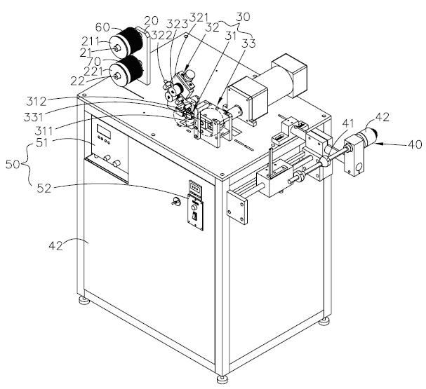
[0024] Such as Figure 1 to Figure 4 As shown, a fuse of the present invention includes a fuse layer 100 and a tin layer 200, the fuse layer 100 is a flat copper wire sheet, and the tin layer 200 is disposed on both sides of the fuse layer 100 , the tin layer 200 is covered by tin wires on the upper and lower surfaces of the fuse layer 100 by thermal melting.

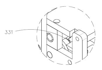
[0025] A device for manufacturing a fuse in the present invention includes a body 10, an outlet frame 20, a hot-melt device 30, a wire take-up frame 40, and a controller 50. The outlet frame 20 is fixed on the upper surface of one side of the body 10, and the outlet Frame 20 comprises tin wire frame 21 and copper wire frame 22, and described ti...


PUM


Abstract

The invention discloses a fuse wire, a device for manufacturing the fuse wire and a manufacturing method of the fuse wire. The device comprises a machine body, a wire outlet frame, a hot melting device, a wire coiling frame and a controller, wherein the wire outlet frame comprises a tin wire frame and a copper wire frame; a tin wire is arranged on the tin wire frame; a copper wire is arranged on the copper wire frame; the hot melting device comprises a heating device and a clamping device; a heating column is arranged on the heating device; the copper wire is attached to the heating column; the clamping device is used for driving the tin wire to extend to the place above the heating column and to be in contact with the copper wire; the controller is arranged on the machine body and is electrically connected with the hot melting device and the wire coiling frame; and the controller is used for controlling the operating temperature of the heating device and the operating speed of the tin wire and the copper wire. Through controlling the operating speed of the tin wire and the copper wire, the hot melting device is used for melting the tin wire onto the copper wire of a laminated structure, so that the middle process is reduced, the process flow is simple, the environmental protection demand is met, the cost is lower, the production efficiency is high, the property is stable and the structure is simple.

Description

technical field [0001] The invention relates to the field of electronic protection components, in particular to a fuse, a device for manufacturing the fuse and a method for manufacturing the fuse. Background technique [0002] Traditional fuses are generally used in electronic products. When the current passing through the fuse is too large, the fuse will be blown to avoid dangers such as overheating and ignition of the circuit. The purpose is to protect people and equipment from injury or even fire due to overcurrent. [0003] There are currently two methods widely used to manufacture fuses, one is the printing and plating process, and the other is threading the wire in the cavity. The printing and plating process provides a method for mass production of fuses. Through the design of the conductive layer pattern, fuses with different currents can be produced, but this process has a fatal flaw, that is, after the printed circuit is sintered and dried, Its compactness is dif...

Claims


Application Information

Patent Timeline
IPC IPC(8): H01H85/055H01H69/02
Inventor 高连忠贺乐远
Owner DONGGUAN BETTER ELECTRONICS TECH
Learn More