
Gas humidifying system for fuel cell testing platform

A test platform and fuel cell technology, applied in the directions of fuel cells, fuel cell additives, electrical components, etc., can solve the problems of unusable fuel cell test platforms, complex systems, and complex structures for fuel cell humidifiers, and achieve online The effect of the automatic replenishment function

Inactive Publication Date: 2012-07-04
KUSN FUERSAI ENERGY
View PDF10 Cites 15 Cited by
  • Summary
  • Abstract
  • Description
  • Claims
  • Application Information

AI Technical Summary

Problems solved by technology

[0014] 1. An integrated fuel cell humidifier cannot be used on a fuel cell test platform, and cannot accurately control RH;
[0015] 2. The fuel cell drum humidification method controls the humidity of the gas through mechanical rotation. The structure is relatively complicated and the humidity of the gas cannot be accurately controlled;
[0016] 3. The spray humidification method is that the water is first gasified in a large boiler and then degassed and combined into the fuel cell; the disadvantage is that the water needs to be atomized first, which consumes a lot of energy, and it is easy to condense in the process of mixing with the gas, which is easy to produce a state of excessive humidification. Humidity is not easy to control;
[0017] 4. The water spray humidification method is to spray water to humidify the fuel cell through the steam-water separation system; the temperature of the humidification water needs heat preservation measures, and the steam-water separation system is used. The system is more complicated and the humidity is not easy to control

Method used


Image

  • Gas humidifying system for fuel cell testing platform
  • Gas humidifying system for fuel cell testing platform
  • Gas humidifying system for fuel cell testing platform

Examples


Embodiment Construction

[0034] The present invention will be further described below in conjunction with the accompanying drawings and embodiments.

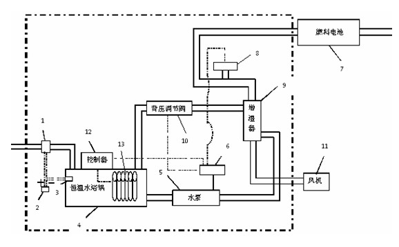
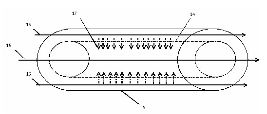
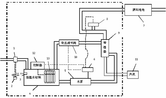
[0035] Such as figure 1 As shown, the multi-stage variable gas humidification system used for the fuel cell test platform, in which the constant temperature water bath 4, the heating rod 13 and the temperature controller 12 can perform multi-stage heating on the humidification water source entering the fuel cell, and the temperature range is 20 ℃-100℃; the water pump 5 and the back pressure regulating valve 10 that can adjust the water flow can realize the control of the water flow and pressure. The tube humidifier 9 is connected to the fuel cell module 6 in series, and the multi-stage heating and humidification flow control can be realized through the water conversion of the perfluorosulfonic acid membrane tube humidifier 9 .

[0036] figure 1 Medium temperature and high humidity temperature and humidity sensor 8 is installed between the fuel cell mo...


PUM


Abstract

The invention relates to a gas humidifying system for a fuel cell testing platform. The gas humidifying system consists of a multistage heating system, an online automatic water replenishing system, a humidifying water flow and pressure control system and a gas temperature and humidity real-time monitoring system. The multistage heating system comprises a constant-temperature water bath kettle, a heating controller and heating rods. A plurality of heating rods used for heating the humidifying water are arranged in the constant-temperature water bath kettle and are connected with the temperature controller to realize multistage temperature regulation from 20 DEG C to 100 DEG C. The gas humidifying system for the fuel cell testing platform has the advantages that the temperature control of the humidifying water can be realized through the multistage heating system, the flow and pressure control function of the humidifying water which passes through a perfluorosulfonate membrane tube humidifier is realized, the online automatic water replenishing function is realized, the detection and feedback functions of a real-time online high-temperature-resistant and high-humidity-resistant temperature and humidity sensor is realized and finally the accurate control of gas humidity is realized through the synergistic effect of the functions.

Description

technical field [0001] The invention relates to a fuel cell test platform, in particular to a gas humidification system for testing a proton exchange membrane fuel cell test platform. Background technique [0002] In today's global energy shortage and high oil prices, it is imperative to find new energy as a substitute for fossil fuels. Fuel cells are considered to be the fourth-generation power generation technology after hydropower, thermal power and atomic power generation. It directly converts the chemical energy of oxidants and reductants into electrical energy through electrocatalytic reactions. It is an efficient, safe, clean and flexible new type of power generation technology. power generation technology. Among them, the proton exchange membrane fuel cell has a wide range of application prospects in ground power stations, electric vehicles and portable power sources due to its remarkable advantages such as high efficiency, high energy density, low reaction temperat...

Claims


Application Information

Patent Timeline
IPC IPC(8): H01M8/04H01M8/04119
CPCY02E60/50
Inventor 顾荣鑫张诗伟张超沈军陶少龙陈凌云徐麟
Owner KUSN FUERSAI ENERGY
Learn More