A plasma cleaning device

A technology for plasma cleaning and cleaning equipment, applied in cleaning methods and utensils, chemical instruments and methods, etc., can solve problems such as uneven plasma, and achieve the effects of achieving uniformity, uniform flow, and improving mixing uniformity.

Active Publication Date: 2020-12-29
BOE TECH GRP CO LTD +1
View PDF5 Cites 1 Cited by
  • Summary
  • Abstract
  • Description
  • Claims
  • Application Information

AI Technical Summary

Problems solved by technology

[0004] The technical problem to be solved by the embodiments of the present invention is to provide a plasma cleaning device to solve the technical problem of uneven plasma ejected from the plasma cleaning device

Method used


Image

  • A plasma cleaning device
  • A plasma cleaning device
  • A plasma cleaning device

Examples


no. 1 example

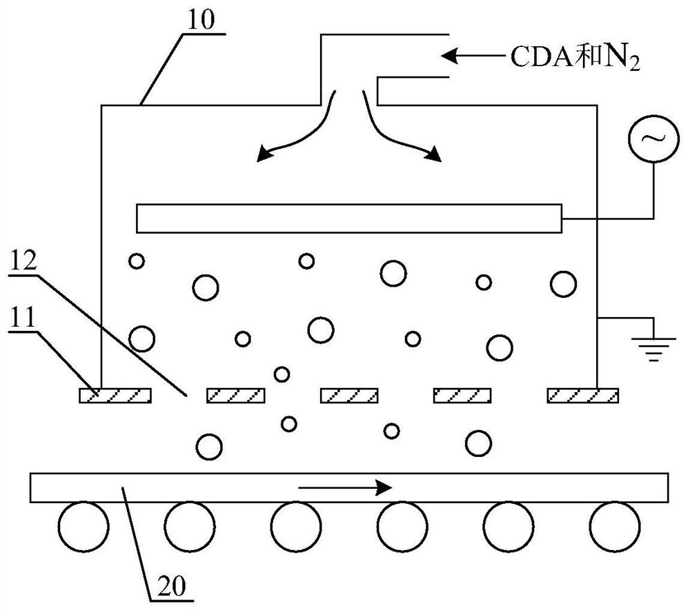
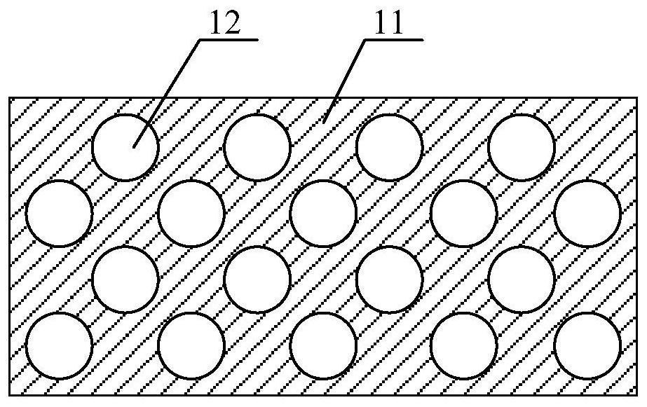
[0042] figure 2It is a schematic structural diagram of the plasma cleaning equipment according to the first embodiment of the present invention. The cleaning device includes a cavity 10 for generating plasma and a baffle structure for ejecting the plasma toward a substrate 20 . The baffle structure includes at least two baffles provided with a plurality of spray holes, and the spray holes on adjacent baffles are interlaced. In this embodiment, the baffle structure includes a first baffle 31 and a second baffle 41 . The first baffle 31 is disposed close to the cavity 10 , and the second baffle 41 is disposed between the first baffle 31 and the substrate 20 . The first baffle 31 is provided with a plurality of first spray holes 32 , the second baffle 41 is provided with a plurality of second spray holes 42 , and the first spray holes 32 and the second spray holes 42 are interlaced.

[0043] In this embodiment, CDA and N are introduced into the chamber 10 from the top of the ...

no. 2 example

[0052] Figure 4 It is a schematic structural diagram of the plasma cleaning equipment according to the second embodiment of the present invention. The main structure of the cleaning equipment of this embodiment is the same as that of the cleaning equipment of the first embodiment, the difference is that, as Figure 4 As shown, the cleaning equipment in this embodiment further includes a first moving device 60 for moving the first baffle 31 .

[0053] In this embodiment, the first moving device 60 makes the first baffle 31 move back and forth in the plane where the first baffle is located, so that the difference in the flow rate between different first nozzle holes 32 can be further eliminated, and the spraying rate to the substrate can be improved. The uniformity of the plasma flow rate, and at the same time further improve the mixing uniformity of different plasmas, eliminate the difference in the cleaning effect of the substrate surface, and improve the quality of the subs...

no. 3 example

[0055] Figure 5 It is a schematic structural diagram of the plasma cleaning equipment according to the third embodiment of the present invention. The main structure of the cleaning equipment of this embodiment is the same as that of the cleaning equipment of the first embodiment, the difference is that, as Figure 5 As shown, the cleaning device in this embodiment further includes a third baffle 51 , and the third baffle 51 is disposed between the second baffle 41 and the substrate 20 . A plurality of third spray holes 52 are arranged on the third baffle plate 51 , and the third spray holes 52 and the second spray holes 42 are interlaced. The third injection holes 52 and the second injection holes 42 are interlaced, which can further mix and diffuse the plasma ejected by different second injection holes 42, eliminate the difference in the flow rate of plasma ejected by different second injection holes 42, and further improve the injection efficiency. The uniformity of the p...


PUM


Abstract

The invention discloses plasma cleaning equipment. The cleaning equipment comprises a cavity used for producing plasmas and a baffle structure enabling the plasmas to eject to a substrate. The bafflestructure comprises at least two baffles provided with multiple ejection holes, and the ejection holes in the adjacent baffles are mutually staggered. The ejection holes in the adjacent baffles in thebaffle structure are mutually staggered, so that the mixing uniformity of different plasmas is improved, the flow differences of plasmas ejected from different ejection holes are eliminated, the flows of plasmas ejecting to the substrate are more uniform, the uniformity of the plasmas ejecting to the substrate is realized, the cleaning effect differences of substrate surfaces are avoided, resulting substrate defects are avoided, and the quality of the substrate is improved.

Description

technical field [0001] The invention relates to the technical field of cleaning substrates in semiconductor and display industries, in particular to a plasma cleaning device. Background technique [0002] In the field of display technology, in the process of substrate preparation, processes such as cleaning, coating, exposure, development, and baking are all performed to form required patterns on the substrate. After the substrate is cleaned, it needs to pass through the plasma cleaning equipment. The plasma ejected from the plasma cleaning equipment combines with the organic matter on the surface of the substrate, and oxidizes and decomposes the organic matter into water and carbon dioxide to remove the organic matter on the surface of the substrate. Therefore, the cleaning effect of the plasma cleaning equipment directly affects the quality of the substrate. [0003] Existing plasma cleaning equipment has the problem of uneven sprayed plasma, resulting in differences in ...

Claims


Application Information

Patent Timeline
Patent Type & Authority Patents(China)
IPC IPC(8): B08B7/00
CPCB08B7/00
Inventor 李晓光冯贺汪栋肖宇
Owner BOE TECH GRP CO LTD
Why Eureka
Try Eureka