
Accumulator control device and method and system for electric auxiliary supply

A control device and auxiliary power supply technology, applied to battery circuit devices, circuit devices, arrangement of multiple synchronous batteries, etc., can solve the problem that the battery is not charged optimally

Active Publication Date: 2012-07-04
PHOENIX CONTACT GMBH & CO KG
View PDF7 Cites 9 Cited by
  • Summary
  • Abstract
  • Description
  • Claims
  • Application Information

AI Technical Summary

Problems solved by technology

[0011] This deviation cannot usually be corrected by the electrical auxiliary power supply, resulting in the battery not being optimally charged

Method used


Image

  • Accumulator control device and method and system for electric auxiliary supply
  • Accumulator control device and method and system for electric auxiliary supply
  • Accumulator control device and method and system for electric auxiliary supply

Examples


Embodiment Construction

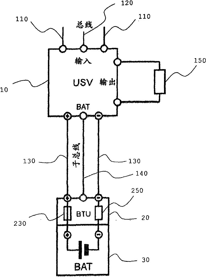
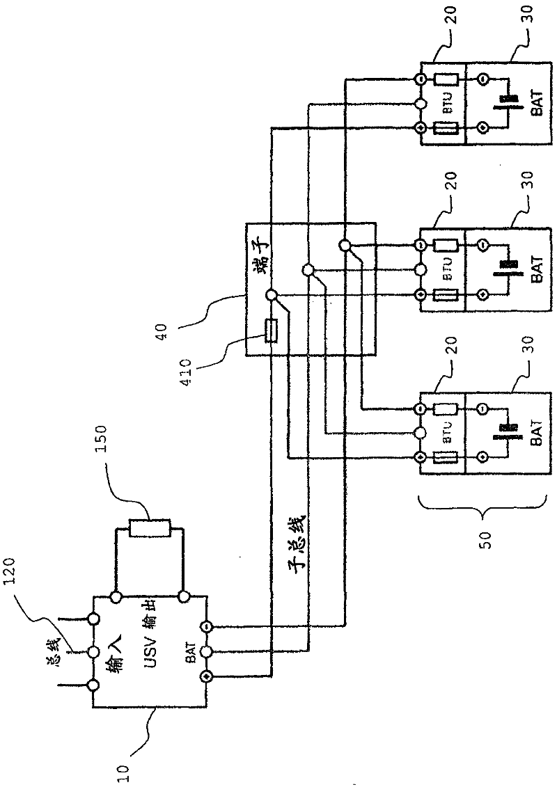
[0041] exist figure 1 A system for auxiliary power supply is shown in , which comprises an auxiliary power supply device 10 for supplying electrical energy to a connected load 150 and for this purpose is connected to the grid via a line 110 . In the event of a grid outage, electrical energy will flow from the rechargeable battery 30 to the load 150, and the battery 30 will be discharged accordingly. When the grid becomes available again, the load 150 is again fed directly from the grid and the battery 30 is charged again. The charging of the battery 30 is performed using a charge termination voltage controlled by the auxiliary power supply device 10, and the charge termination voltage is preferably set according to the battery type, battery voltage, and battery temperature.

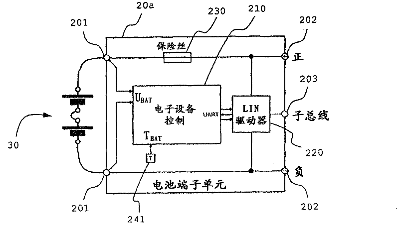
[0042] The battery control device 20 connected in series for the battery 30 transmits the parameters required for an optimal charging process to the auxiliary power supply device 10 via the bus 140. The ...


PUM


Abstract

In order to improve control of charging and / or discharging of a storage battery used in electric auxiliary supply, the invention specifies a storage battery control device (20) connected with a remote auxiliary electric power supply device (10) of electricity at distance, the storage battery control device comprises a communication interface (220) connecting a control unit (210) measuring and analyzing the storage battery parameter with the remote auxiliary electric power supply device (10), wherein the control unit (210) is designed to transmit the measured parameter value to the auxiliary power supply device (30). The invention specifies a system used for auxiliary power supply and a method for controlling the system.

Description

technical field [0001] This invention relates generally to uninterruptible power supply systems operating from batteries. In particular, the invention relates to optimal control of the charging and discharging of the accumulators used in such systems. Background technique [0002] Uninterruptible power supply (USV) systems are used in many electrical installations for ensuring the operation of electrical installations independently of disturbances in the power supply network. USV is used to provide auxiliary power supply when the normal power supply is disturbed. The term "auxiliary power supply" is therefore also used below for the USV. [0003] For the auxiliary power supply, accumulators are usually used, which are connected to the auxiliary power supply and auxiliary supply electrical energy to the loads connected to the auxiliary power supply. A battery is a storage of electrical energy, usually based on an electrochemical system, consisting of one or more secondary ...

Claims


Application Information

Patent Timeline
Patent Type & Authority Applications(China)
IPC IPC(8): H02J7/00H02J9/00
CPCH02J9/066H02J7/0091H02J2007/0098H01M10/441H02J7/0016H01M2010/4271H01M10/4207H01M10/425H01M10/443H01M10/48H01M10/486H01M10/4257Y02E60/10H02J7/007192H04L61/5038G01R31/389G01R31/364G01R31/382G01R31/396G01R31/36H01M10/46
Inventor H·汉科尔M·海因曼A·诺恩多夫M·瓦特博格
Owner PHOENIX CONTACT GMBH & CO KG
Learn More