Supercharge Your Innovation With Domain-Expert AI Agents!

Converter device

A technology of converters and inductors, applied in the field of converters, can solve problems such as static biasing of gates

Inactive Publication Date: 2012-07-04
OSRAM GMBH
View PDF5 Cites 4 Cited by
  • Summary
  • Abstract
  • Description
  • Claims
  • Application Information

AI Technical Summary

Problems solved by technology

In this case the auxiliary supply for the driver Dr only operates when the switch M is switching periodically and therefore provides no static bias to the gate

Method used


Image

  • Converter device
  • Converter device
  • Converter device

Examples


Embodiment Construction

[0043] In the following description, numerous specific details are given to provide a thorough understanding of the embodiments. These embodiments may be practiced without one or several of the specific details, or with other methods, components, materials, and the like. In other instances, well-known structures, materials, or operations are not shown or described in detail to avoid obscuring aspects of the embodiments.

[0044] Reference throughout this specification to "one embodiment" or "an embodiment" means that a particular feature, structure, or patent described in connection with the embodiment is included in at least one embodiment. Thus, appearances of the phrases "in one embodiment" or "in an embodiment" in various places in the specification are not necessarily all referring to the same embodiment. Furthermore, the particular features, structures or characteristics may be combined in any suitable manner in one or more embodiments.

[0045] The headings provided h...


PUM


Abstract

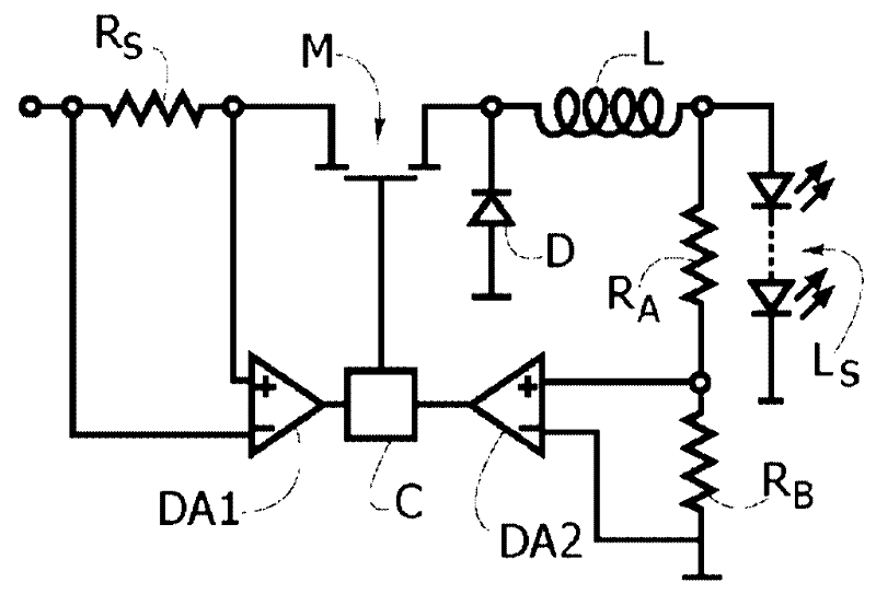
A converter for feeding a load via an inductor with a current having a controlled intensity between a maximum level and a minimum level may include: a switch switchable on and off to permit or prevent, respectively, feeding of current towards said inductor; first and second current sensors sensitive to the current flowing through said switch when said switch is on or off, respectively; comparator circuitry to identify if the current intensity detected by said first current sensor and said second current sensor reaches said maximum level and said minimum level, respectively, by generating respective logical signals; and drive circuitry for said switch sensitive to said logical signals and configured to turn off said switch when the current intensity detected by said first sensor reaches said maximum level and turning on said switch when the current intensity detected by said second current sensor reaches said minimum level.

Description

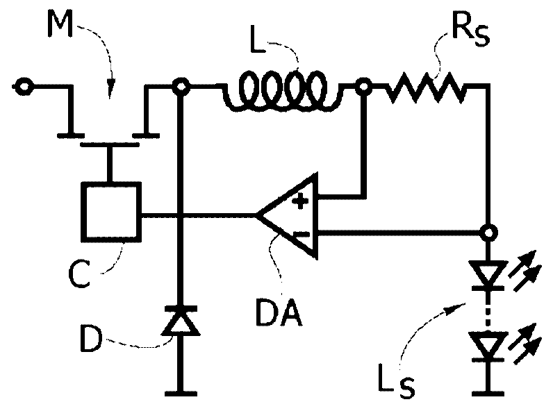
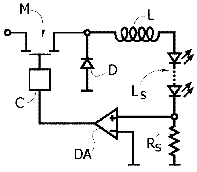
technical field [0001] The invention relates to converters, eg for powering loads such as eg light emitting diodes (LEDs). Background technique [0002] In this context as outlined above, various solutions can utilize well-known designs of "buck" converters (ie, where current is supplied to the load via an inductor), which may not have The output capacitor and / or may have a constant current control strategy rather than the typical constant voltage control strategy, whereby here "constant" current means "average constant" current, i.e., oscillating and always comprised between the two limit values The current within , thus the average value over time is constant. [0003] figure 1 and 3 Various solutions are shown to achieve a control function of the type described above, while Figure 4 and 5 Various ways are shown for driving switches or electronic switches such as Metal Oxide Semiconductor Field Effect Transistors (MOSFETs). [0004] In all figures, the load L fed fr...

Claims


Application Information

Patent Timeline
IPC IPC(8): H02M3/155H05B44/00
CPCH05B33/0818H05B45/375H05B47/25
Inventor 弗朗切斯科·安杰林保罗·德安娜
Owner OSRAM GMBH
Features
  • R&D
  • Intellectual Property
  • Life Sciences
  • Materials
  • Tech Scout
  • Unparalleled Data Quality
  • Higher Quality Content
  • 60% Fewer Hallucinations
Learn More