
System, method and multiplexer for testing radio frequency for base station

A radio frequency test system and radio frequency test technology, applied in wireless communication, electrical components and other directions, can solve the problems of high test environment cost, electromagnetic stray, passive intermodulation difference, etc., to simplify the test environment, reduce the test cost, The effect of improving test efficiency

Inactive Publication Date: 2012-07-04
ZTE CORP
View PDF9 Cites 7 Cited by
  • Summary
  • Abstract
  • Description
  • Claims
  • Application Information

AI Technical Summary

Problems solved by technology

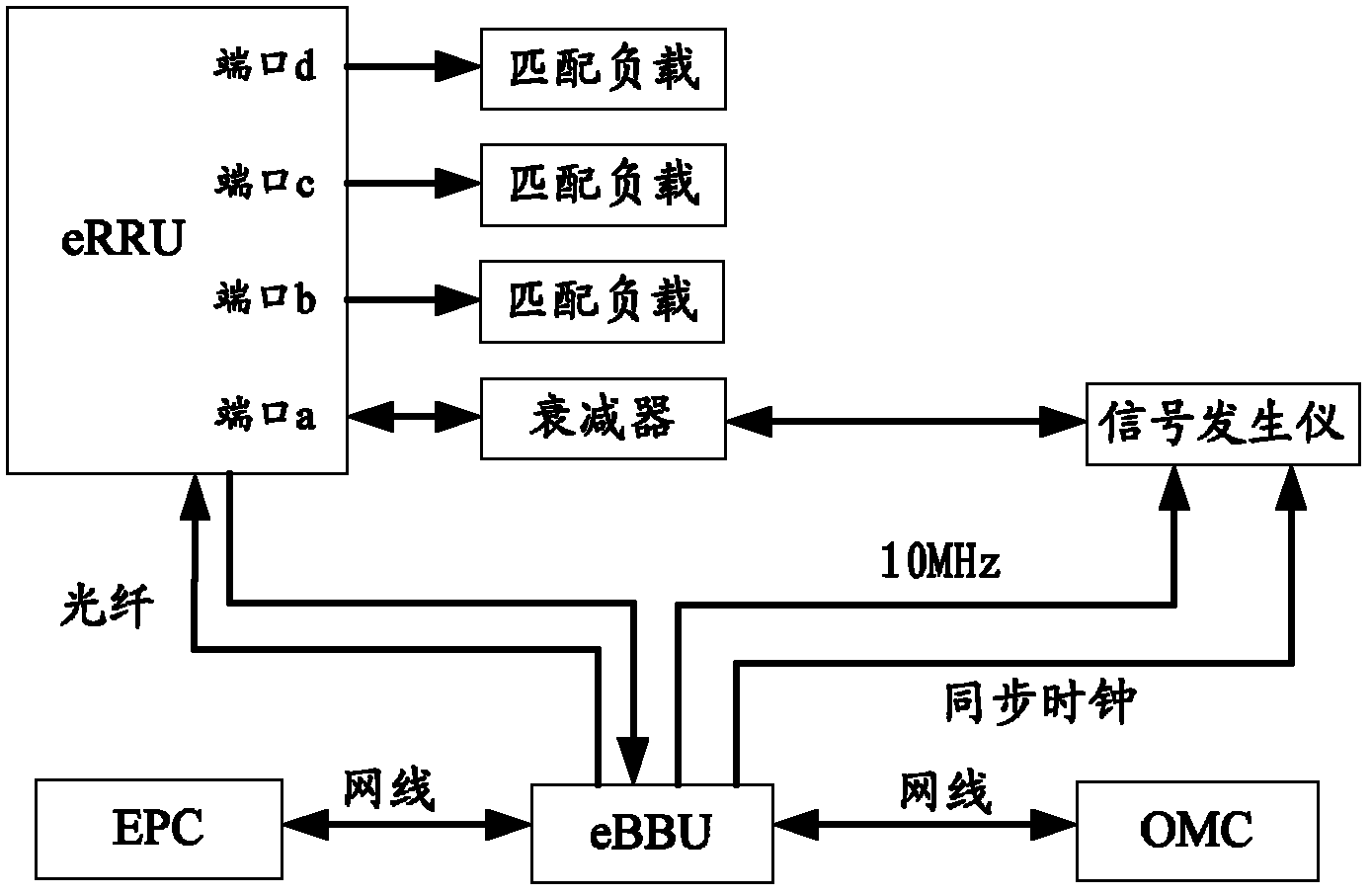
[0004] The laboratory test environment such as figure 2 As shown, in the laboratory test, since the output power of each antenna feed port (that is, the radio frequency port) of the eRRU is greater than 20W, many test accessories are often used, such as attenuators, circulators, isolators and traps. However, the passive intermodulation of ferrite devices such as circulators and isolators is very poor, and the intermodulation products are very large under high power, which has a great impact on the test of eRRU, and the test environment can no longer truly reflect the eRRU. actual performance
[0005] In addition, in the above test environment, the uplink radio frequency index (receiver radio frequency index) and downlink radio frequency index (transmitter radio frequency index) are time-sharing tests, and the efficiency is relatively low
[0006] Moreover, the current RF test environment of FDD LTE uses discrete devices, the connection is complex, the cost of building a test environment is high, and intermodulation and electromagnetic spurs are easily generated at the connection, which has a great impact on the test results.

Method used


Image

  • System, method and multiplexer for testing radio frequency for base station
  • System, method and multiplexer for testing radio frequency for base station
  • System, method and multiplexer for testing radio frequency for base station

Examples


Embodiment Construction

[0042] In order to make the object, technical solution and advantages of the present invention clearer, the present invention will be described in detail below with reference to the accompanying drawings and specific embodiments.

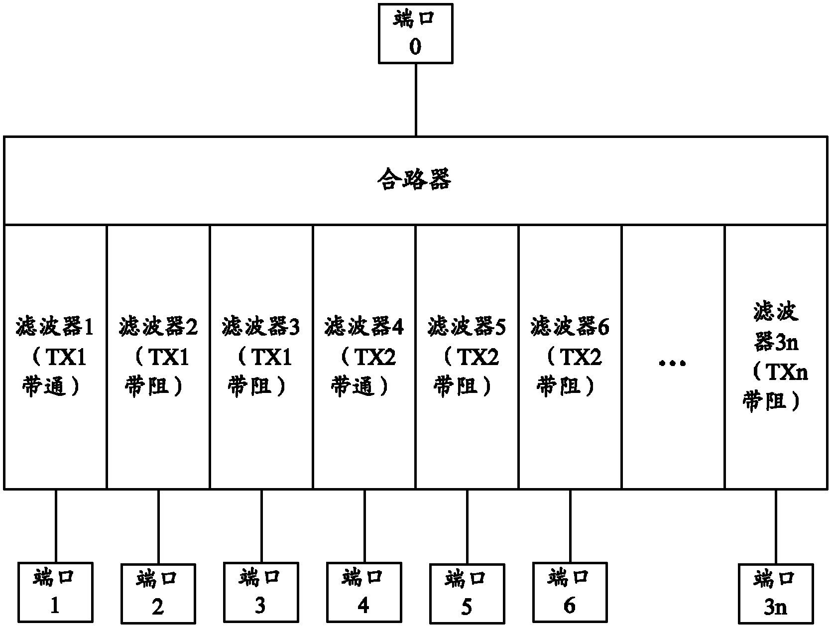
[0043] The present invention aims at the current FDD LTE RRU uplink radio frequency index and downlink radio frequency index time-sharing, the test environment has a great influence on the RRU performance, and the RRU radio frequency test environment has a high accessory cost investment, and designs a multiplexer for radio frequency testing. Using the multiplexer to test the radio frequency performance of the RRU can ensure that the test environment truly reflects the performance of the RRU, and can simultaneously test the uplink radio frequency index and the downlink radio frequency index.

[0044] image 3 is a schematic structural diagram of a multiplexer according to an embodiment of the present invention. refer to image 3 , the multiplexer c...


PUM


Abstract

The invention provides a system, a method and a multiplexer for testing radio frequency for a base station. The multiplexer comprises a first port, a first combiner, at least a second port, at least a third port, a band-pass filter and a band elimination filter. The first port is connected with a radio frequency port to be tested of the base station, the first combiner is connected with the first port, the second port is connected with a frequency spectrum analyzer, and the third port is connected with a signal generator. The band-pass filter is connected between the first combiner and the second port, and a passing band of the band-pass filter is a downlink radio frequency signal frequency range of the base station. The band elimination filter is connected between the first combiner and the third port, and a stop band is a downlink radio frequency signal frequency range of the base station. The system, the method and the multiplexer can improve accuracy of testing efficiency and testing results and reduce testing cost.

Description

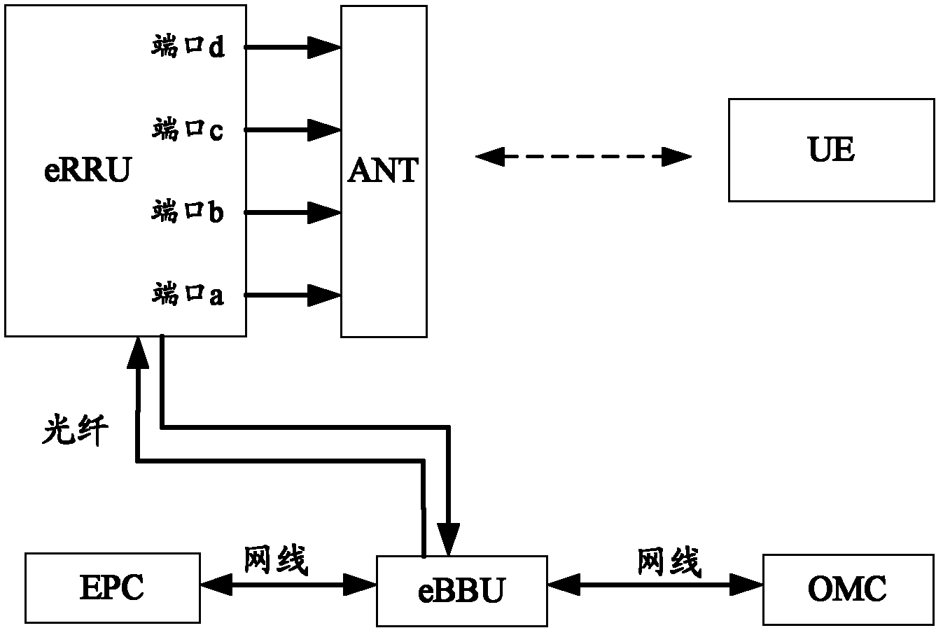
technical field [0001] The invention relates to wireless communication equipment testing technology, in particular to a radio frequency testing system, method and multiplexer of a Frequency Division Duplex Long Term Evolution (FDD LTE) base station. Background technique [0002] The evolved remote radio unit (eRRU) in the LTE base station is an indispensable part of the wireless communication system. Its performance affects the entire system. It needs to be tested to verify whether its radio frequency performance has reached the design goal. [0003] The actual deployment scenario of eRRU is as follows: figure 1 as shown, figure 1 Among them, ANT is an antenna, UE is a user equipment, EPC is an evolved packet core network, and OMC is an operation and maintenance center. When the eRRU is actually deployed in the field, the eRRU is directly connected to the antenna through the feeder. Since the passive intermodulation between the antenna and the RF feeder is usually below -1...

Claims


Application Information

Patent Timeline
Patent Type & Authority Applications(China)
IPC IPC(8): H04W24/02
CPCH04W24/02H04W24/06
Inventor 成军平田宏余飞张天鹏刘彬张志锋邵立群
Owner ZTE CORP
Learn More