Electric appliance control box

An electrical control box and splint technology, applied in electrical components, electrical equipment shells/cabinets/drawers, cooling/ventilation/heating renovation, etc., can solve the problem of uneven heat dissipation of the box, and achieve the effect of uniform heat dissipation

Inactive Publication Date: 2012-07-04
SHANGHAI MICRO ELECTRONICS EQUIP (GRP) CO LTD
View PDF3 Cites 4 Cited by
  • Summary
  • Abstract
  • Description
  • Claims
  • Application Information

AI Technical Summary

Problems solved by technology

[0004] In summary, the disadvantage of the electrical control box of the prior art is that the heat dissipation of the electrical control box is not uniform

Method used


Image

  • Electric appliance control box
  • Electric appliance control box
  • Electric appliance control box

Examples


Embodiment 1

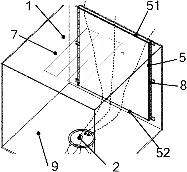
[0020] like figure 1 As shown, the electrical control box of the present invention includes a first air inlet 1 arranged on the first side wall 7, an air outlet 2 arranged on the second side wall 9, and the air outlet 2 is connected with a suction pipe 3 , the suction pipe 3 is connected with a suction device 4, and also includes a splint 5, the splint 5 is installed in parallel on one of the remaining side walls, and a gap 8 is left between the splint 5 and the remaining side wall One end of the slit 8 is provided with a second air inlet 51, the second air inlet 51 is close to the first air inlet 1, and the other end of the slit 8 is provided with an air guide 52 capable of flowing to the air outlet 2, the The air guiding port 52 is close to the air outlet 2 . Wherein the suction device 4 is a blower fan.

Embodiment 2

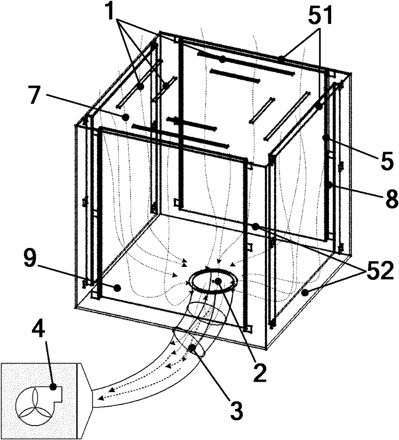
[0022] like figure 2 As shown, this embodiment 2 is improved on the basis of embodiment 1, and its distinguishing technical feature is that it includes a plurality of splints 5, and the splints 5 are installed in parallel on multiple surfaces of the remaining side walls. That is to say, the difference between Embodiment 2 and Embodiment 1 is the number of splints 5 installed.

[0023] In the above two embodiments, the second air inlet 51 , the slit 8 , the air guide 52 , and the air outlet 3 constitute the second heat dissipation air duct. During use, electrical components are installed on the side wall of the splint 5 of the electrical control box. Start the suction device 4, and the new constant temperature air is sucked from the second air inlet of the second heat dissipation air duct, and flows through the side wall of the splint 5 (that is, the splint with electrical components) of the heat generating part through the gap 8 and the air guide port 52 and the box. The si...

Embodiment 3

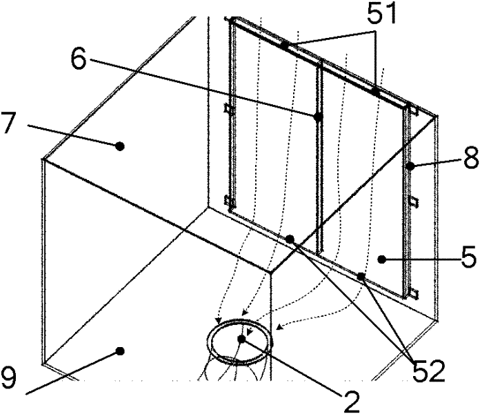
[0027] like image 3 As shown, Embodiment 3 is improved on the basis of Embodiment 1. Its heat dissipation principle is the same, and the difference lies in the structural change. Specifically, it is vertically arranged between the splint 5 and the remaining side wall of the electrical control box. There is a rib 6.


PUM


Abstract

The invention discloses an electric appliance control box which comprises first air inlets (1), an air outlet (2) and at least one clamp plate (5), wherein the first air inlets (1) are arranged in a first side wall (7); the air outlet (2) is arranged on a second side wall (9); the clamp plates (5) are arranged in parallel on at least one surfaces of the residual side walls; gaps (8) are reserved between the clamp plates (5) and the residual side walls; second air inlets (51) are arranged at one ends of the gaps (8); the second air inlets (51) are close to the first air inlets (1); air guide ports (52) capable of guiding air to flow to the air outlet (2) are arranged at the other ends of the gaps (8); and the air guide ports (52) are close to the air outlet (2). Due to the adoption of the electric appliance control box disclosed by the invention, a box body of the electric appliance control box can be subjected to uniform heat dissipation.

Description

technical field [0001] The invention relates to an electrical control box, in particular to an electrical control box applied to photoetching machines in the field of semiconductor manufacturing. Background technique [0002] Electrical equipment, mechatronic equipment or mechatronic equipment all use electrical control boxes, especially electrical control boxes for lithography machines, which contain power devices, integrated circuit chips, and various electronic devices for laser equipment. Because all kinds of electrical components in the electrical control box are heating devices, when the equipment is used, various electrical components will emit heat. When the ambient temperature in the electrical control box is too high, electrical components may stop working or be damaged. Electrical components are generally installed on the side walls of the electrical control box. Therefore, the side walls where the electrical components are installed will also generate high heat,...

Claims


Application Information

Patent Timeline
Patent Type & Authority Applications(China)
IPC IPC(8): H05K5/00H05K7/20
Inventor 张洪博杨志斌余斌金敏
Owner SHANGHAI MICRO ELECTRONICS EQUIP (GRP) CO LTD
Why Eureka
Try Eureka