Ultrasound transducer with improved adhesion between layers

An ultrasonic transducer and adhesive technology, applied in ultrasonic/sonic/infrasonic diagnosis, instruments, sonic diagnosis, etc., can solve problems such as poor adhesion

Inactive Publication Date: 2012-07-11
GENERAL ELECTRIC CO
View PDF4 Cites 3 Cited by
  • Summary
  • Abstract
  • Description
  • Claims
  • Application Information

AI Technical Summary

Problems solved by technology

[0005] Known ultrasound transducers configured as shown in FIGS. 5A , 6A and 7A have been found to exhibit poor adhesion between the conductive layer 504 and the de-matching layer 506 at the ground area 604

Method used


Image

  • Ultrasound transducer with improved adhesion between layers
  • Ultrasound transducer with improved adhesion between layers
  • Ultrasound transducer with improved adhesion between layers

Examples


Embodiment Construction

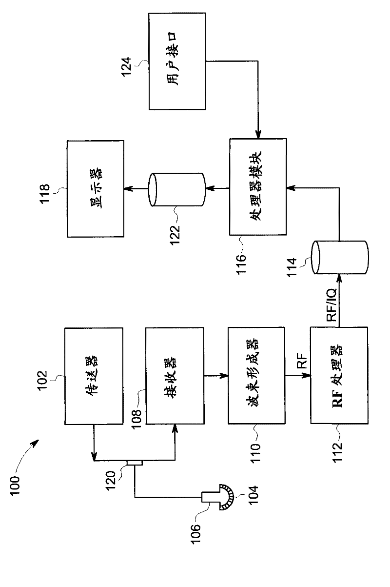
[0026] The foregoing summary, as well as the following detailed description of certain embodiments of the invention, will be better understood when read in conjunction with the accompanying drawings. In order to illustrate the invention, certain embodiments are shown in the figures. It should be understood, however, that the invention is not limited to the arrangements and instrumentalities shown in the drawings. To the extent that the figures illustrate diagrams of the functional blocks of various embodiments, the functional blocks are not necessarily indicative of the division between hardware circuitry. Thus, for example, one or more of the functional blocks (eg, a processor or memory) may be implemented in a single piece of hardware (eg, a general-purpose signal processor or random access memory, hard disk, etc.). Similarly, a program can be a stand-alone program, combined as a subroutine in an operating system, a function in an installed software package, and so on. It ...


PUM


Abstract

The invention relates to an ultrasound transducer with improved adhesion between layers, and provides ultrasound transducers and methods of forming ultrasound transducers. The ultrasound transducer can include an acoustic stack (520) including: a dematching layer (526) and a flexible circuit including a nonconductive layer (522) and a conductive material (524). The conductive material (524) can include a plurality of substantially parallel strips. Adhesive (525) can be provided between the dematching layer (526) and the flexible circuit such that it contacts the strips of conductive material (524) and portions of the nonconductive layer (522) between the strips of conductive material (524). A plurality of substantially parallel cuts (528) can extend through the dematching layer (526), through the adhesive (525) and into the nonconductive layer (522) without cutting into the strips of conductive material (524). The flexible circuit can include a ground area and the strips of conductive material (524) and cuts (528) can be located thereon. The adhesive (525) can encapsulate each strip of conductive material on three surfaces, including a top surface (620) and two sides of each strip.

Description

technical field [0001] Embodiments of the present technology relate generally to ultrasonic transducers, and more specifically, to bonding between layers of material in acoustic stacks for ultrasonic transducers. Background technique [0002] Figure 5A shows a perspective view of the layers of an acoustic stack 500 of a prior art ultrasound transducer. Acoustic stack 500 includes a plurality of layers 505, including a dematching layer 506, and includes a non-conductive layer 502 (eg, including ) and a conductive layer 504 (eg, comprising copper) flex circuit. Conductive layer 504 is secured to dematching layer 506 using adhesive 505 (shown in FIG. 7A ), and a dicing operation is then performed to provide a plurality of substantially parallel cuts 508 through dematching layer 506, conductive layer 504, and to the In the conductive layer 502 . [0003] FIG. 6A shows a top view of a portion of the top surface 600 of the flexible circuit of the prior art ultrasound transduce...

Claims


Application Information

Patent Timeline
IPC IPC(8): A61B8/00
CPCA61B8/00G01S7/52084B06B1/0622A61B8/4427A61B8/4405A61B8/46A61B8/483Y10T29/49005
Inventor R·盖龙J-P·马拉克里达
Owner GENERAL ELECTRIC CO
Why Eureka
Try Eureka