Multi-channel water cleaning double-component gluing head
A technology of water cleaning and gluing head, which is applied in the direction of coating, liquid coating device on the surface, etc. It can solve the problems that water cannot be used for cleaning, and achieve the effect of reducing cleaning times, reducing pollution and improving stability
- Summary
- Abstract
- Description
- Claims
- Application Information
AI Technical Summary
Problems solved by technology
Method used
Image
Examples
specific Embodiment approach 1
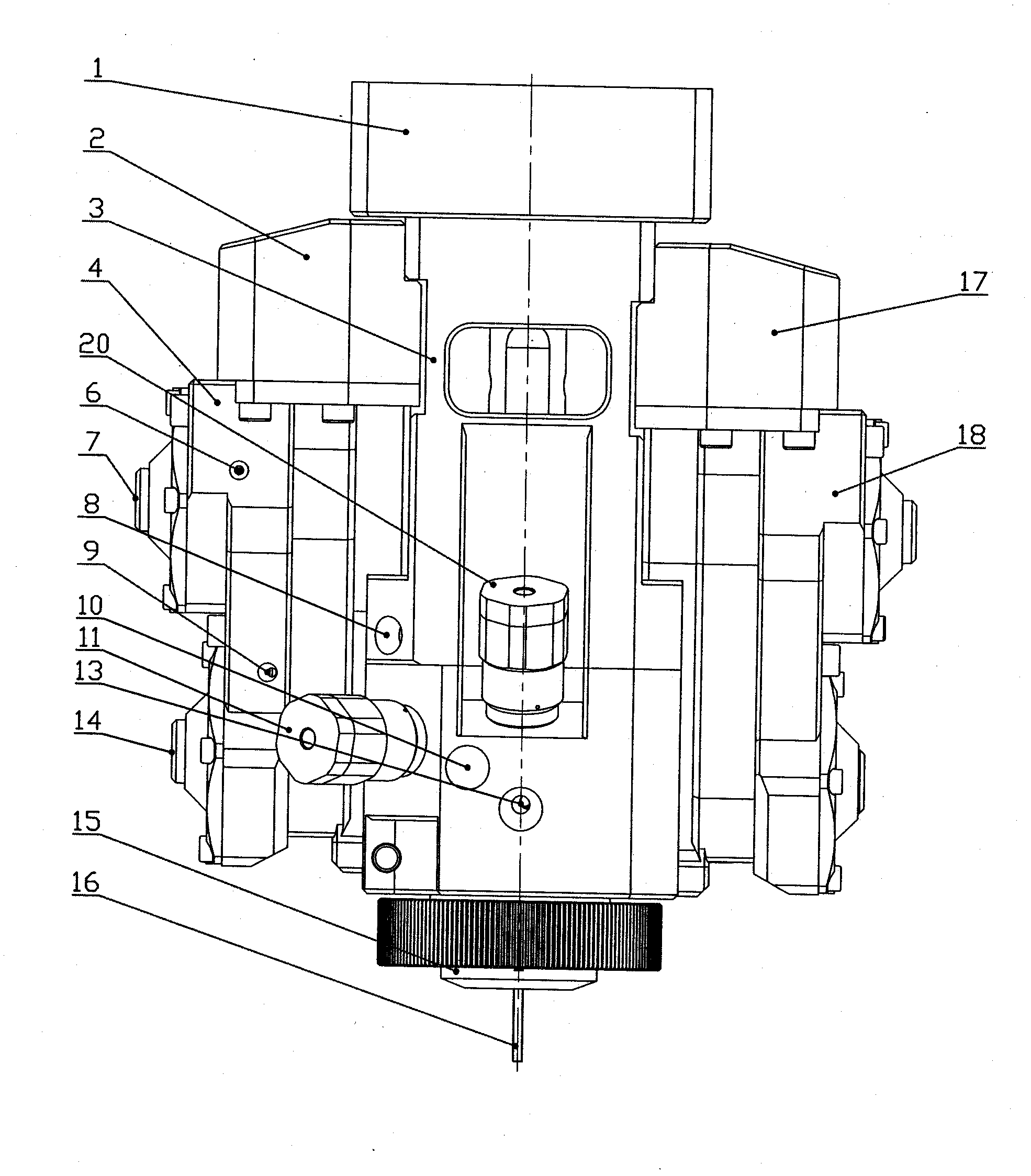
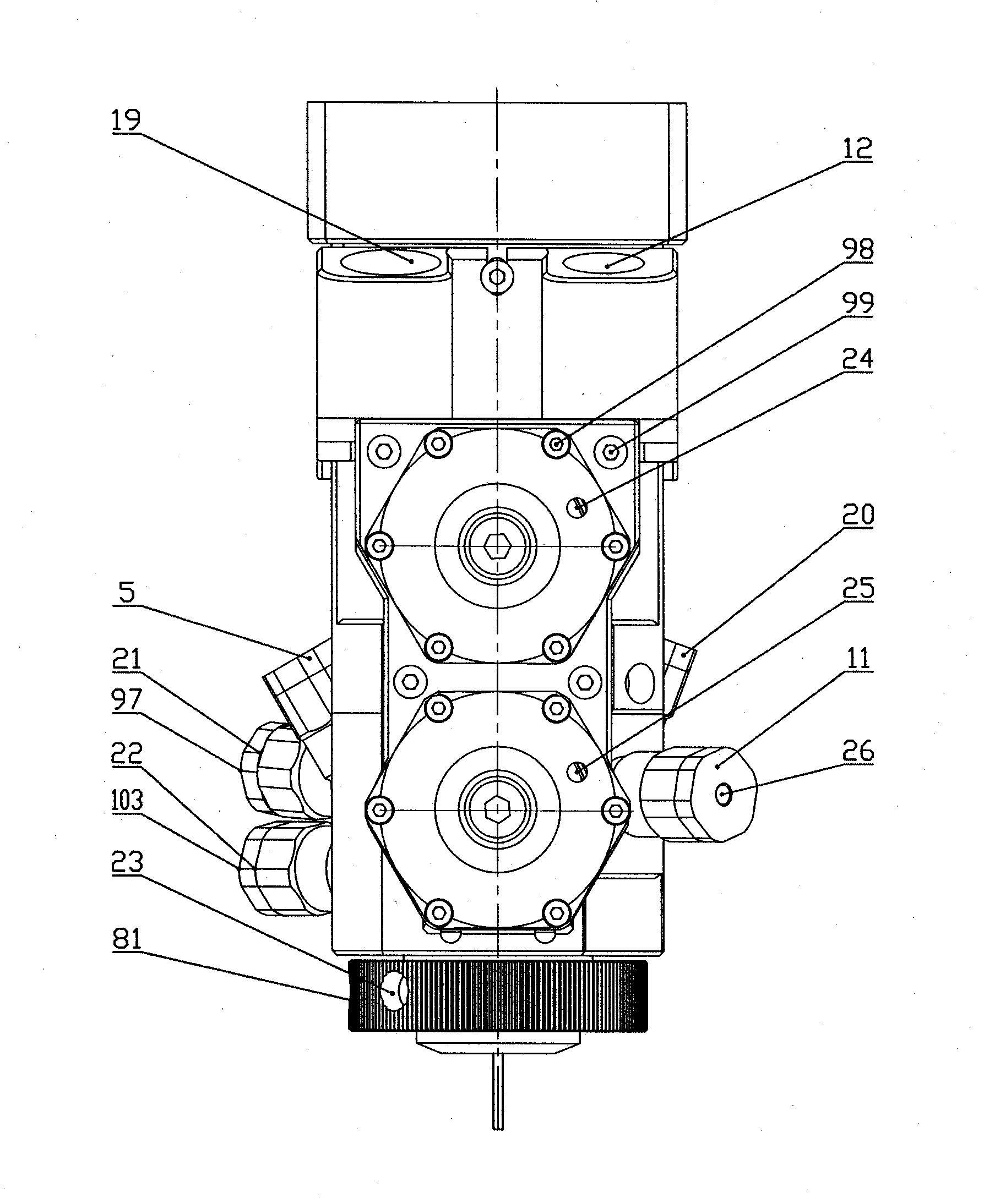
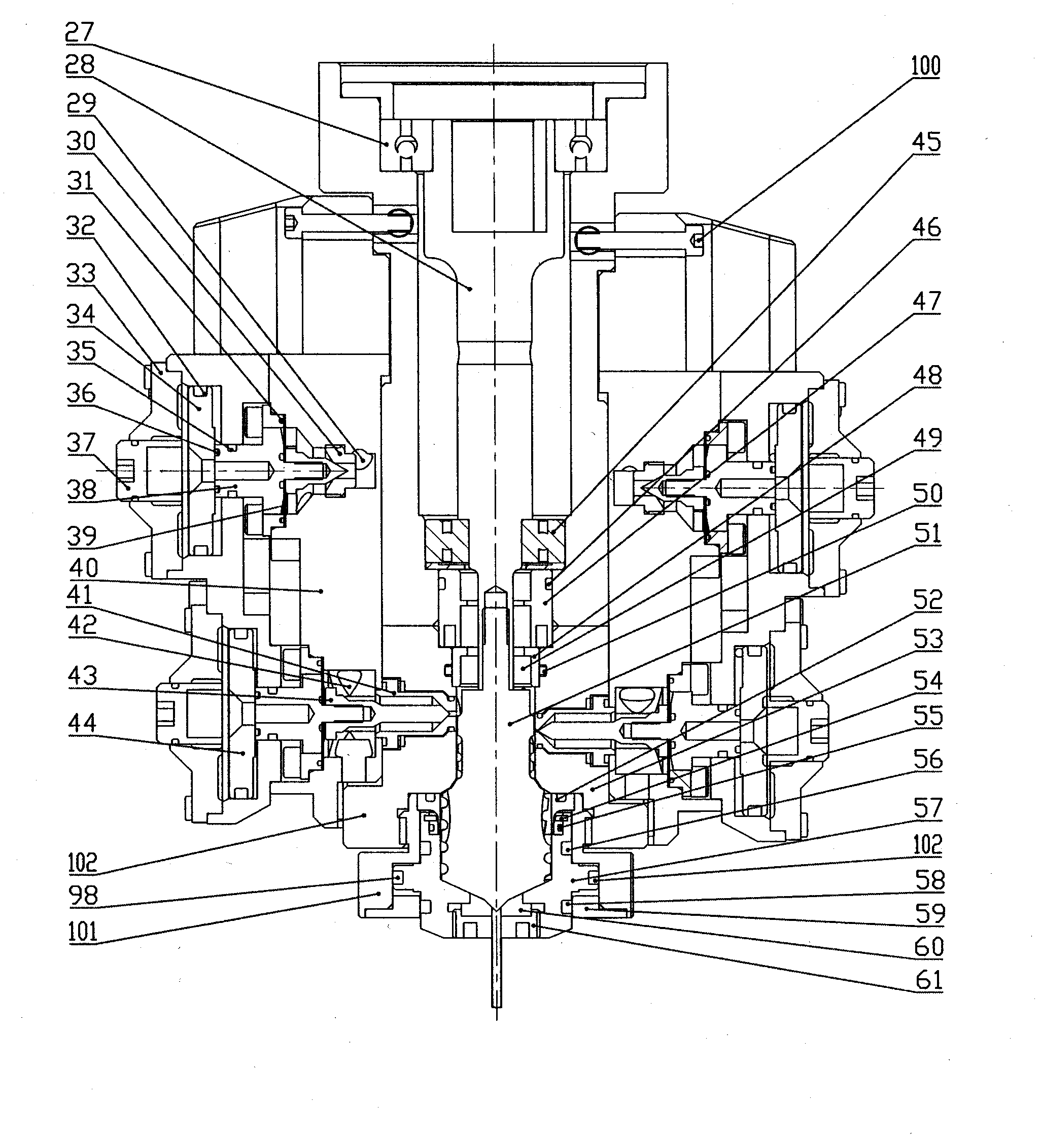
[0017] Specific implementation mode one: as Figure 1 to Figure 7 As shown, the main shaft part 1, the main valve body 3, the stirring blade 51, the polyurethane A component inlet, the overflow port seat 2, the polyurethane B component inlet, the overflow port seat 17, the polyurethane A glue inlet valve 4, Polyurethane B glue feed valve 18, water cleaning valve 1, water cleaning valve 2 11, water cleaning valve 3 21, water cleaning valve 4 22, cup moving part 15, pneumatic components, glue nozzle 16, etc. The main body of the water-cleaning two-component glue applicator is fixed and integrated. When the valve needle 2 43 and valve needle 73 are opened at the same time, the glue of the two components of polyurethane A and B is continuously supplied by the metering pump, and the glue of polyurethane A and The glue inlet valve 4 and the polyurethane B glue inlet valve 18 enter the glue cavity 68 of the mixing cup of the glue applicator, and the motor or hydraulic motor drives th...
specific Embodiment approach 2
[0021] Specific implementation mode two: as figure 1 , figure 2 , image 3 , Figure 5 and Figure 7 As shown, the polyurethane component A feed port described in this embodiment, the overflow port 2, the polyurethane A glue inlet valve 4, the A glue valve seat 40, the polyurethane component inlet, the overflow port seat 17, the polyurethane B glue glue inlet valve, The stirring blade seat 102 is connected to the main valve body 3 by screws, the sealing ring 1 31, the rubber diaphragm 39 and the sealing ring 35 are installed on the relief valve needle 1 38, the sealing ring 2 32 is installed on the piston 1 34, and the valve cover 33 is fixed on the polyurethane A glue feed valve 4, the piston 34 can move left and right, the stroke adjustment screw 37 is installed on the valve cover 33, and the opening size of the overflow valve needle 38 can be adjusted by turning the stroke adjustment screw 37, thereby adjusting the overflow valve. Flow rate: the sealing ring 31 and the...
specific Embodiment approach 3
[0022] Specific implementation mode three: as figure 1 , figure 2 , image 3 As shown, the water-cleaning two-component gluing head described in this embodiment has a cup-moving structure. The cup moving structure means that the closing of the gluing nozzle 16 depends on the movement of the outer cup, so that the moving cup 57 and the conical surface of the stirring blade 51 form a sealing surface, so that the mixed glue stops flowing out of the gluing nozzle 16. The cup moving part 15 is mainly composed of sealing ring eight 52, cup body 53, retaining ring 54, sealing ring nine 55, sealing ring ten 56, moving cup body 57, sealing ring fourteen 98, sealing ring eleven 58, valve cover 59, Glue nozzle 60, air hole four 23, air hole eight 81 and plug 61 form. The compressed air communicates with air hole four 23 and air hole eight 81 respectively, and is arranged on the upper and lower sides of the protruding part of the moving cup body 57. The compressed air pushes the movin...
PUM
 Abstract
Description
Claims
Application Information
 - R&D
- Intellectual Property
- Life Sciences
- Materials
- Tech Scout
- Unparalleled Data Quality
- Higher Quality Content
- 60% Fewer Hallucinations
Browse by: Latest US Patents, China's latest patents, Technical Efficacy Thesaurus, Application Domain, Technology Topic, Popular Technical Reports.
© 2025 PatSnap. All rights reserved.Legal|Privacy policy|Modern Slavery Act Transparency Statement|Sitemap|About US| Contact US: help@patsnap.com


