Bore machining cutter head and bore machining cutting tool

A technology of cutter heads and tools, which is applied in the field of cutting tools for inner diameter processing, can solve the problems of reduced brazing area, reduced brazing strength, and peeling of cutting edges, and achieves the effects of suppressing peeling, low-cost manufacturing, and high brazing strength

Inactive Publication Date: 2012-07-11
KYOCERA CORP
View PDF7 Cites 0 Cited by
  • Summary
  • Abstract
  • Description
  • Claims
  • Application Information

AI Technical Summary

Problems solved by technology

[0007] However, in the methods of brazing the cutting edge portion of the tool body as in Patent Documents 2 and 3, when the diameter of the tool body is reduced for small-di

Method used


Image

  • Bore machining cutter head and bore machining cutting tool
  • Bore machining cutter head and bore machining cutting tool
  • Bore machining cutter head and bore machining cutting tool

Examples


Embodiment Construction

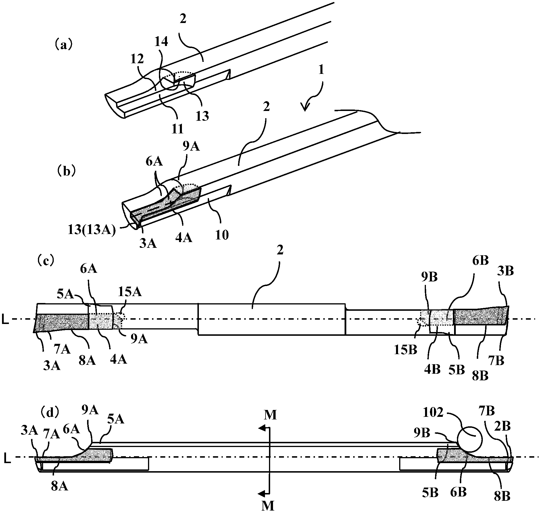
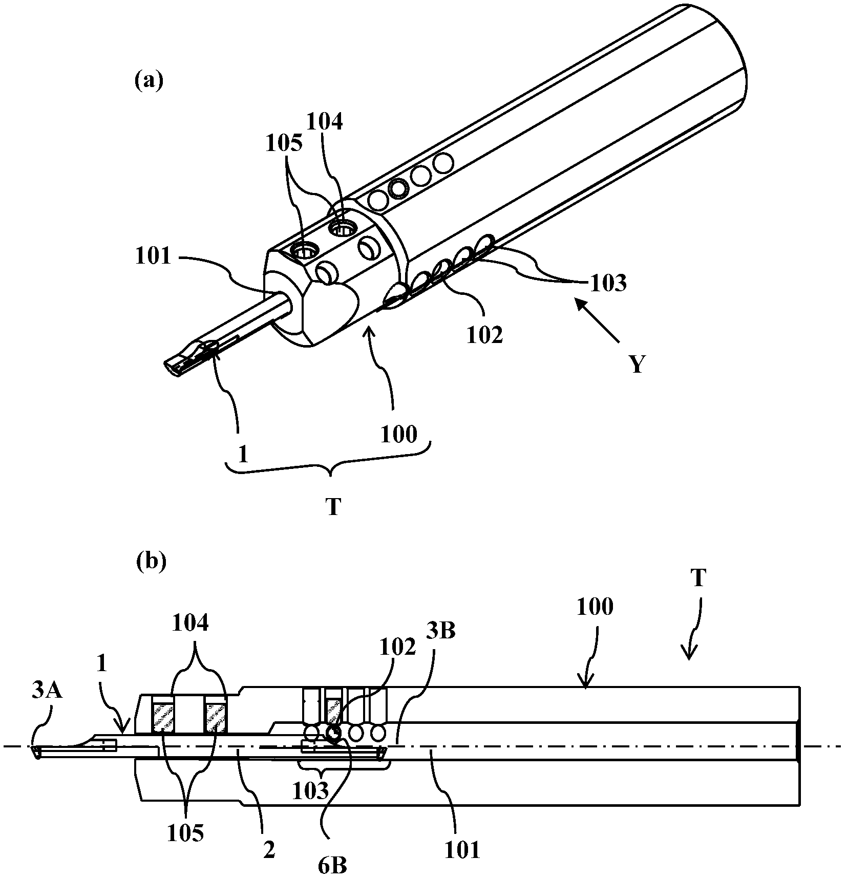
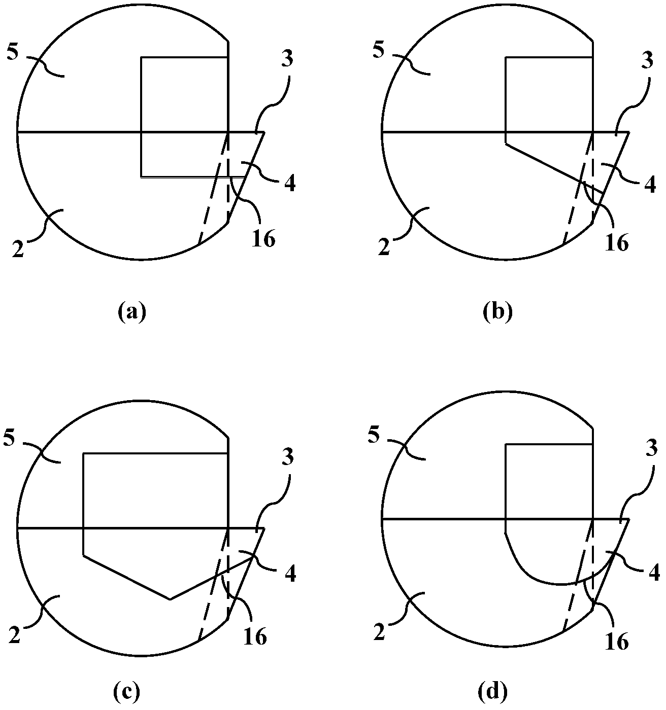
[0043] Below, use Figure 1 ~ Figure 4 Next, a cutting tool T for inner diameter machining that is used by attaching an inner diameter machining tip (hereinafter, sometimes referred to as a tip) 1 according to an embodiment of the present invention to an arbor 100 will be described. exist figure 1 Among them, (a) is a perspective view of the tool body before inserting the cutting edge bit of the inner diameter machining bit, (b) is a perspective view of main parts, (c) is a plan view, and (d) is a side view. figure 2 An example of the cutting tool for inner diameter processing in which the tip 1 is attached to the holder 100 is shown, (a) is a perspective view, and (b) is a side view. image 3 It shows the front end view of the cutting tool for inner diameter machining which attached the bit for inner diameter machining to the holder, and is a figure to which the tip for inner diameter machining of the bottom surface shape of (a)-(d) is attached. Figure 4 An example of a c...


PUM


Abstract

The invention provides a bore machining cutter head and a bore machining cutting tool, which are cheap to manufacture and high in brazing strength. The bore machining cutting tool (T) is formed by installing a bore machining cutter head (1) onto a cutter rod (100). The bore machining cutter head (1) comprises a rod-shaped tool body (2); and a cutter head (4) of a cutting edge (3) protruded to the side (17) out of the rod-shaped tool body (2) with the lower surface (16) thereof arranged on the tool body (2). The lower surface (16) and the upper surface (18) of the cutter head (4) of the cutting edge (3) are partially clamped by the tool body (2). The upper surface (18) of the cutter head (4) of the cutting edge (3) is partially brazed to the tool body (2).

Description

technical field [0001] The present invention relates to an inner diameter machining bit and a cutting tool for inner diameter machining suitable for inner surface machining of a small-diameter hole provided with the inner diameter machining bit. Background technique [0002] As a cutting tool for machining an inner diameter of a hole, for example, as in Patent Document 1, a shape in which a cutting edge is formed on a side of a tip of a rod-shaped body is widely used. Cutting tools of the above-mentioned shape tend to have a smaller cutting edge in order to cope with small-diameter machining, and the other parts are hardly damaged, and the life of the cutting edge is often reached. Therefore, a more effective method of use is desired. [0003] On the other hand, Patent Documents 2 and 3 disclose a cutting tool for inner diameter machining. A cutting edge portion having a single crystal diamond blade is brazed to the front end of the tool body (tool head, shank). The cutting...

Claims


Application Information

Patent Timeline
IPC IPC(8): B23B27/18B23B27/20
Inventor 中园阳二
Owner KYOCERA CORP
Why Eureka
Try Eureka