
Method for producing threaded screws with large bearing locations
A screw and longitudinal technology, applied in the field of manufacturing screw, can solve the problem of not being able to transmit loads for a long time, and achieve the effect of avoiding waste
- Summary
- Abstract
- Description
- Claims
- Application Information
AI Technical Summary
Problems solved by technology
Method used
Image

Examples
Embodiment Construction
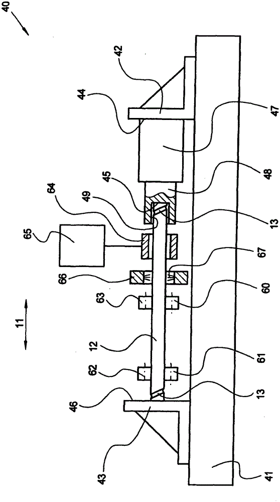
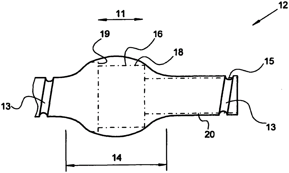
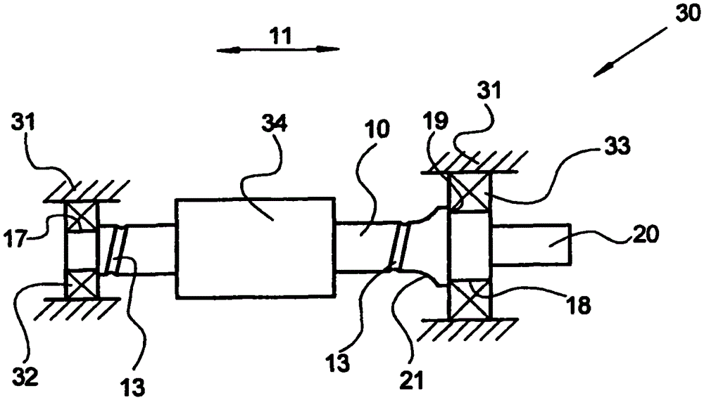
[0027] figure 1 A side view of a schematically simplified illustration of a device 40 for carrying out the method according to the invention is shown. The device 40 includes a solid base frame 41 which extends parallel to the longitudinal direction 11 of the blank 12 . A first and a second identical stop angle bracket 42 , 43 are fastened on the base frame 41 in a position-adjustable manner in the longitudinal direction 11 , so that the device 40 can be adapted to different lengths of the blank 12 . The flat stop surfaces 44 of the stop angle brackets 42 , 43 are oriented perpendicularly to the longitudinal direction 11 and face each other. On the stop surface 44 of the first stop angle 42 is fastened a hydraulic cylinder 47 whose piston rod 48 is displaceable in the longitudinal direction 11 . Instead of the hydraulic cylinder 47, a mechanical drive, in particular an electric cylinder, can also be provided, for example equipped with a particularly high load-carrying planeta...
PUM
| Property | Measurement | Unit |
|---|---|---|
| diameter | aaaaa | aaaaa |
Abstract
Description
Claims
Application Information