
Isostatic Forming Mold And Isostatic Forming Method Thereof

A forming mold and press forming technology, which is applied in the field of light guide plate forming devices, can solve the problems of uneven pressure, difficult template pressure, uneven softening of imprinted objects, etc., and achieve the effect of improving efficiency and uniform heat transfer

Inactive Publication Date: 2012-07-11
CHENMING MOLD IND CORP
View PDF3 Cites 6 Cited by
  • Summary
  • Abstract
  • Description
  • Claims
  • Application Information

AI Technical Summary

Problems solved by technology

[0003] The pressurizing device in the prior art uses oil pressure, air pressure or other drivers as the source of output pressure, and cooperates with the crankshaft or shaft to directly connect the imprinting mold to apply pressure to the template. Compared with the shaft that transmits pressure, the template has a large area. plane, so the pressure transmitted by the axis to the template can be regarded as point pressure, so it is not easy to make the template fully compressed, so the pressure on the imprinted product that is pressed through the template is not uniform, so the imprinted product The yield rate is not easy to improve, and the size of the imprinted product can only be formed into a small-sized product. Later, there will be a multi-axis pressure device and the use of a silicone plate as a buffer material, and the effect will only be slightly improved.
[0004] And the known heating device drills a waterway on the upper first template or the imprinting mold, and then heats or cools the imprinted object with hot liquid or cold liquid; or heat pipes and waterways are crossed, and the heat pipes are used for heating The imprinted object is then passed through a cold liquid to cool the imprinted object in a waterway. The above-mentioned known heating methods all need to heat the imprinting mold body first, and then transfer the heat energy to the imprinted object through heat conduction. The thermal energy of this method Due to the size of the imprinting mold, the position of the heating pipe or the embedding of the waterway, and the size of the imprinted object, the transfer is easy to cause uneven transfer speeds, and then the phenomenon of uneven softening of the imprinted object occurs. Therefore, the quality of the imprinted product is good. The efficiency is not easy to increase, so based on the above reasons, the inventor of the present invention thought and designed a pressure equalization molding die and a pressure equalization molding method, in order to improve the deficiencies of the existing technology, and then enhance the implementation and utilization of the industry

Method used


Image

  • Isostatic Forming Mold And Isostatic Forming Method Thereof
  • Isostatic Forming Mold And Isostatic Forming Method Thereof
  • Isostatic Forming Mold And Isostatic Forming Method Thereof

Examples


Embodiment Construction

[0042] Below in conjunction with specific embodiment and accompanying drawing, further set forth the present invention:

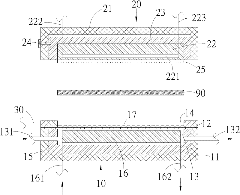
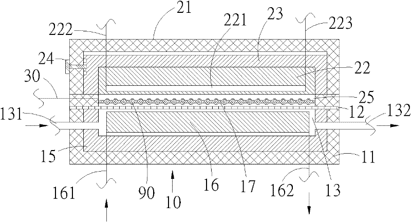
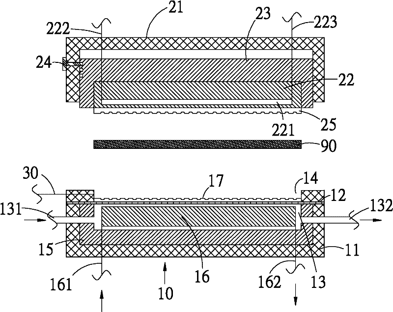
[0043] Such as figure 1 and figure 2 As shown, the present invention is a isostatic molding mold, which comprises a first mold 10 , a second mold 20 and at least one vacuum control pipeline 30 in a preferred embodiment.

[0044]The aforementioned first mold 10 includes a first main shell 11, which may be made of metal, and the first main shell 11 is recessed with a first container on its upper working surface side. chamber, and the first chamber is provided with an elastic heat conduction mold 12 transversely from an opening, and the elastic heat conduction mold 12 further divides the first chamber into a hydraulic tank 13 located inside the elastic heat conduction film 12 and a hydraulic tank 13 located inside the elastic heat conduction film 12 The mold cavity 14 on the outside of the elastic heat conducting film 12, and a first heat insulating layer 1...


PUM


Abstract

The present invention discloses an isostatic forming mold and an isostatic forming method thereof. The isostatic forming mold comprises the following components: a first mold which is provided with a hydraulic tank and a mold chamber, wherein the hydraulic tank is internally provided with a temperature control coil pipe and the mold chamber is provided with a first mold plate; and a second mold which corresponds with the first mold and can be matched with the first mold for forming a whole mold. Furthermore the second mold is provided with a second mold plate which corresponds with the first mold plate. According to the isostatic forming mold, a purpose of performing press printing on the surface of a light guide plate uniformly can be obtained through performing hydrualic pressing and heating on the inner part of the hydraulic tank.

Description

technical field [0001] The invention relates to a pressure-equal forming mold and a pressure-equal forming method thereof, in particular to a light guide plate forming device and method for uniformly pressurizing a temperature-controlling liquid. Background technique [0002] The known thermocompression molding method of light guide plate (LGP) mainly places the object to be imprinted in the cavity of an imprinting mold. The imprinting mold includes a set of upper first templates, each of which has a pressing On the embossing surface of the printed optical texture, the imprinted object is placed between the surfaces of the upper first template with embossed optical textures and then the imprinting mold is closed. At this time, the upper first template will form a closed mold cavity, and the imprinted object is It exists in this closed mold cavity. After the imprinting mold is closed, the imprinting mold will be heated to soften the imprinted object to a plastic state, and th...

Claims


Application Information

Patent Timeline
Patent Type & Authority Applications(China)
IPC IPC(8): B29C59/02B29L11/00
Inventor 庄元立
Owner CHENMING MOLD IND CORP
Learn More