Vehicle-mounted electronic control apparatus

A vehicle-mounted electronic control and equipment technology, which is applied to vehicle components, circuits or fluid pipelines, transportation and packaging, etc., can solve the problem of inability to erase data, etc.

Inactive Publication Date: 2012-07-11
DENSO CORP
View PDF7 Cites 9 Cited by
  • Summary
  • Abstract
  • Description
  • Claims
  • Application Information

AI Technical Summary

Problems solved by technology

However, when the RAM 10 is replaced with a nonvolatile memory, data cannot be erased by disconnecting the battery 5

Method used


Image

  • Vehicle-mounted electronic control apparatus
  • Vehicle-mounted electronic control apparatus
  • Vehicle-mounted electronic control apparatus

Examples


no. 1 example

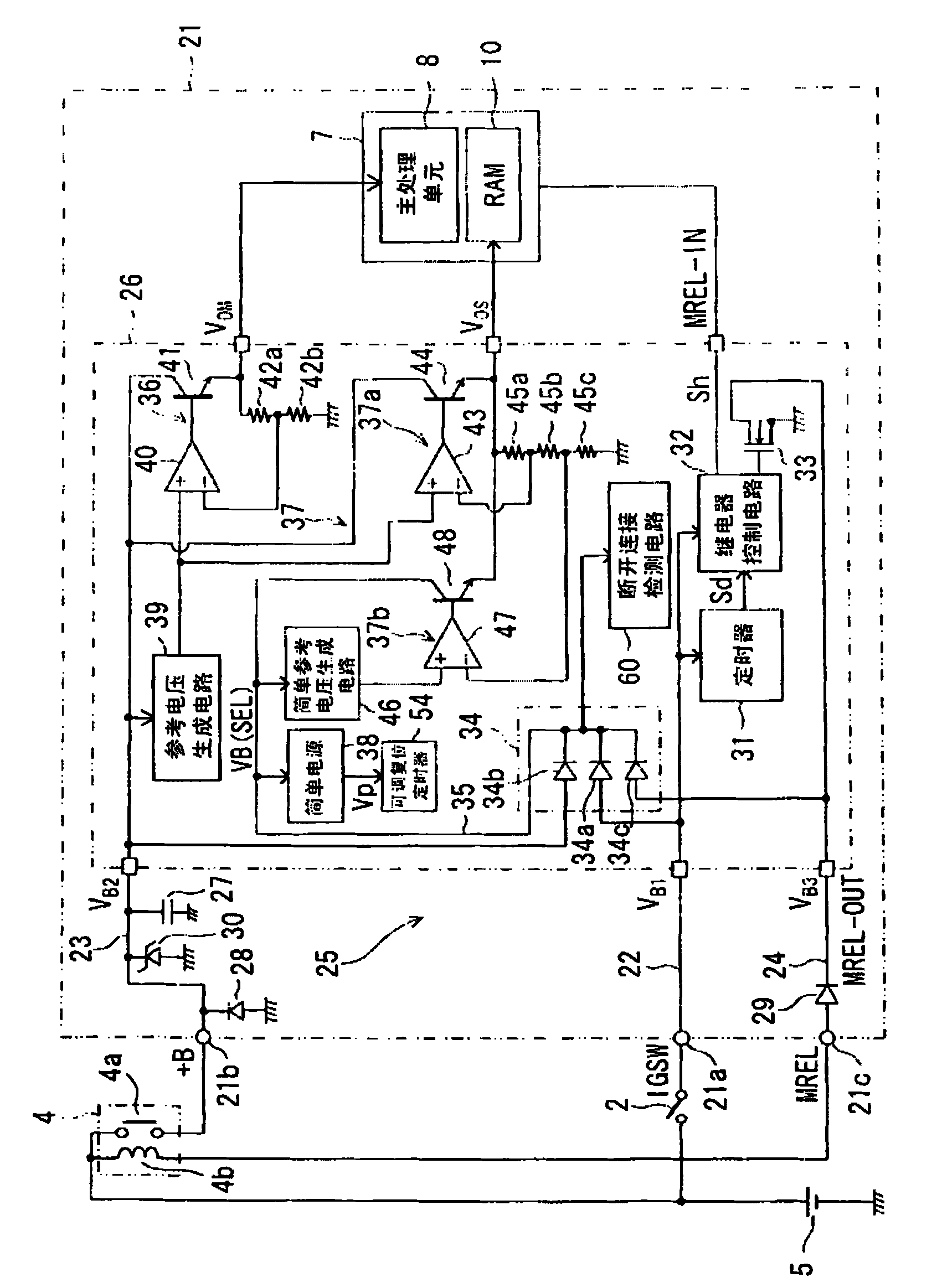
[0049] First refer to figure 1 , the vehicle is provided with an ignition switch 2 that turns on and off a voltage from a battery 5 and a main relay (power supply relay) 4 in response to the ignition switch 2 being turned on and off.

[0050] Terminals 21a, 21b, and 21c of an electronic control unit (ECU) 21 are power supply terminals provided in a first power supply line 22, a second power supply line 23, and a third power supply line 24, respectively. The first power line 22 is connected to the positive terminal of the battery 5 through the ignition switch 2 . The second power supply line 23 is connected to the positive terminal of the battery 5 through a normally open contact 4 a of the main relay 4 . The third power supply line 24 is connected to the positive terminal of the battery 5 through the coil 4 b of the main relay 4 . The voltages of the first power line 22, the second power line 23 and the third power line are determined by V B1 , V B2 and V B3 express. Th...

no. 2 example

[0075] Except that the configuration related to engine startup is different as well figure 1 The second embodiment is similar to the first embodiment except that the shown timer 31 is not provided in the power supply device 25 .

[0076] The engine start system in the second embodiment is a one-push system in which the engine is started or stopped by a user who operates a push-button engine start switch provided in the vehicle. When the engine start switch (equivalent to the ignition switch in the first embodiment) is pressed, a trigger signal is sent to the power supply device, whereby the power supply device transmits an engine start request signal to the authentication control unit. The authentication control unit checks the user ID of the portable device with the master ID of the vehicle and allows ignition when they match each other. The configuration of this engine starting system is well known and therefore will not be described in detail.

[0077] The second example...

no. 3 example

[0080] except as Image 6 The third embodiment is similar to the first embodiment ( figure 1 ).

[0081] The selection circuit 34 uses the power supply lines 23 and 24 as inputs, and selects a power supply line having a higher voltage among them. It outputs the selected voltage V to the power line 35 (output line) B(SEL) (Specifically, the voltage at which the forward voltage Vf of the diodes 34a, 34c is reduced). The capacitor 64 is connected between the power supply line 35 and ground, which is located outside the power supply IC 26 . When the voltage of the first power line 22 V B1 When rising, the relay control circuit 32 turns on the MOSFET 33 to turn on the main relay 4 .

[0082] The third embodiment is for example Figure 7 Proceed as shown. When the battery 5 is electrically connected at time t21 , the selection circuit 34 selects the power supply line 24 having a higher voltage from the power supply lines 23 and 24 . That is, the battery voltage VB of the ba...


PUM


Abstract

The invention provides a vehicle-mounted electronic control apparatus (21), which comprises a selection circuit (34). The selection circuit is connected with the voltage of the first power supply line (22) of a battery (5) through an ignition switch (2) and is also connected with the voltage of the second power supply line (23) of the battery (5) through the normally open contact (4a) of a main relay (4). The selection circuit is also connected with the voltage of the third power supply line (24) of the battery (5) through the coil (4b) of the main relay (4). Then the highest voltage among the above three voltages is adopted by the selection circuit. The selection circuit can continue provide the voltage of the battery to a power supply line (35) regardless of the on-off state of the ignition switch. Meanwhile, circuits, such as the RAM (10) of a micro computer (7) and the like, can be continuously operated by the selection circuit. In addition, a flash (135) can be initialized through a simplified operation, wherein the battery is disconnected and then is connected again.

Description

technical field [0001] The present invention relates to an on-vehicle electronic control device that controls the supply of electric power from a battery regardless of the state of an ignition switch. [0002] The present invention also relates to an on-vehicle electronic control device that initializes data in a nonvolatile memory when an operation is started after a battery is disconnected and connected again. Background technique [0003] Conventional vehicle-mounted electronic control devices disclosed in Patent Documents 1, 2, etc., such as Figure 10 configured as shown in the example. [0004] [Patent Document 1] JP 2005-307851 A (US 2005 / 0236900 Al) [0005] [Patent Document 2] JP 2006-105001 A (US 2006 / 0072365 Al) [0006] In this conventional in-vehicle electronic control device, an electronic control device (hereinafter referred to as ECU) 1 that controls a vehicle engine turns on a main relay 4 through a drive circuit 3 when an ignition switch 2 is turned on. ...

Claims


Application Information

Patent Timeline
Patent Type & Authority Applications(China)
IPC IPC(8): B60R16/03
Inventor 吉田顺一佐竹弘之小栗隆雅吉峰誉人山田祐司山口惇中野崇明泽田朋一
Owner DENSO CORP
Why Eureka
Try Eureka