Column type water cap

A technology of water cap and column type, which is applied in the field of water cap of sewage treatment equipment, can solve the problems of narrow use range, poor water quality circulation, non-detachable, etc., and achieve improved operation efficiency, uniform water distribution effect, and convenient repeated use Effect

Active Publication Date: 2012-07-11
南通友邦金塑制品有限公司
View PDF4 Cites 0 Cited by
  • Summary
  • Abstract
  • Description
  • Claims
  • Application Information

AI Technical Summary

Problems solved by technology

The various types of water caps currently used in China are either integral and cannot be disassembled; or the components of the water caps are assembled with interference fit and strong fit. Yes, but the assembly is cumbersome and requires professional technicians. At the same time, it needs to be tested by the inspector before it can be used.
The water caps of various structures used in China listed above, due to structural defects and single functions of the water caps, are not convenient, reliable, and cost-saving for users.
In addition, the water caps currently used in China have the problem of dead angle at the bottom of the cap. There is a liquid level difference between the lowest inlet and drainage gaps at the bottom of the water cap and the orifice plate of the equipment, resulting in poor water quality circulation in the blind area, and the water quality is not fresh and easy to cause Secondary pollution, affecting water quality and safety
[0003] All in all, there are many series of water cap products in China, which have problems such as single performance, design defects in functions, narrow use range, such as small temperature application range, and limited corrosion resistance.
As a result, the selection range of water caps for users is small, and some users have high water quality requirements and highly corrosive environments. There is no suitable water cap product to deal with, which seriously affects the normal production and operation of users.

Method used


Image

  • Column type water cap
  • Column type water cap
  • Column type water cap

Examples


Embodiment Construction

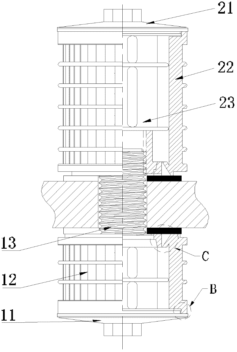
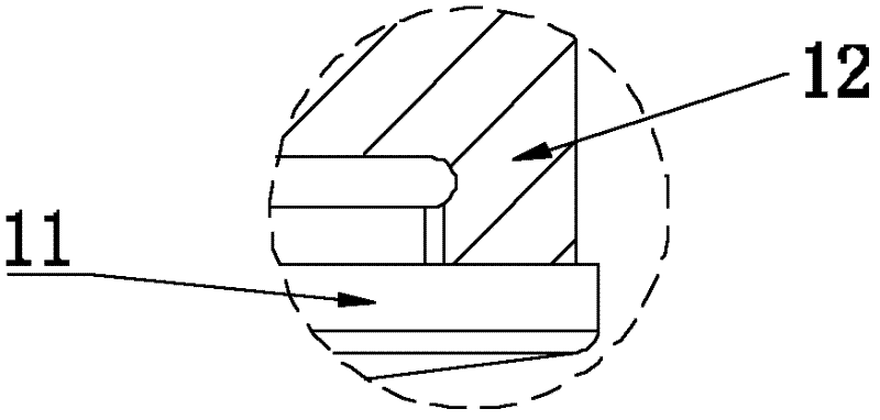
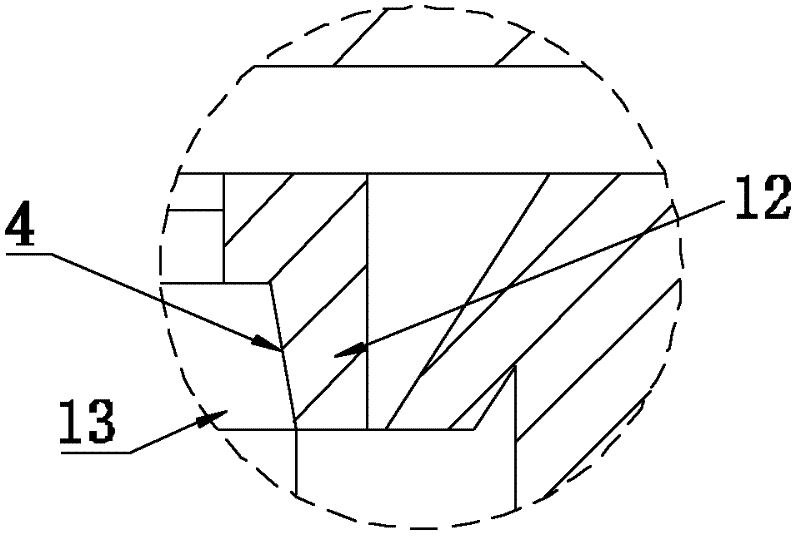
[0033] Such as figure 1 Shown is a specific embodiment of the present invention, which is a nested combination installation of two sets of water caps made of PVDF fluorine material that can be installed independently. One group includes a cap 11, a cap body 12 and a screw rod 13. The cap body 12 is a cylindrical overall structure with a ring-shaped protrusion on its outer surface. In order to enhance the overall design, vertical gaps are evenly distributed on the outer surface and a ring shape is evenly distributed on the bottom surface. Gap, the spacing of the annular gap is 0.25mm, and the vertical gap on the outer side of the cap body communicates with each other, the top of the screw rod 13 is fixedly connected with the cap 11, the upper part of the cap body 12 and the cap 11 are assembled and connected by snap buttons, the screw The bottom of 13 passes through the bottom of the cap body 12, and has at least a conical joint surface 4 with the bottom of the cap.

[0034] T...


PUM


Abstract

The invention discloses a water cap, which comprises a cap cover, a cap body and a screw. The cap body is of a column integral structure. Vertical gaps are evenly distributed on the outer lateral face of the cap body, the top of the screw is fixedly connected with the cap cover, the cap body and the cap cover adopt the snap button mode to conduct assembly and connection, the lower portion of the screw penetrates through the cap bottom of the cap body, and at least one conical combination face is arranged between the lower portion of the screw and the cap bottom. The water cap can be combined and installed by sleeving two groups of water caps in embedding mode. Compared with the prior art, the combination position of the cap body of the water cap and the cap cover on the top portion of thescrew adopts the combination location design of a snap button, the screw and the cap bottom adopt conical combination, so that the water cap has better sealing performance and is not stressed excessively in assembly and disassembly. No quality problem exists even laypeople operates. Therefore, the water cap is really light, convenient, reliable and capable of being cleaned and used repeatedly, greatly improves operation effect of users and reduces production cost.

Description

technical field [0001] The invention relates to the technical field of water treatment, in particular to a water cap of sewage treatment equipment. Background technique [0002] Water cap, as the core component of water treatment equipment, is widely used in electric power, petrochemical, pharmaceutical, food and other industries. The various types of water caps currently used in China are either integral and cannot be disassembled; or the components of the water caps are assembled with interference fit and strong fit. Yes, but the assembly is cumbersome and requires professional technicians. At the same time, it needs to be tested by the inspector before it can be used. The above-listed water caps of various structures used in China cannot be convenient, reliable and cost-effective for users due to structural defects and single functions of the water caps. In addition, the water caps currently used in China have the problem of dead angle at the bottom of the cap. There is...

Claims


Application Information

Patent Timeline
Patent Type & Authority Applications(China)
IPC IPC(8): C02F1/00
Inventor 丁宝书
Owner 南通友邦金塑制品有限公司
Why Eureka
Try Eureka