Floating oil absorber
An absorber and oil slick technology, applied in the directions of grease/oily substance/float removal device, liquid separation, separation method, etc., can solve the problems of difficult manual cleaning, high labor intensity, water pollution, etc. Simple, easy to manufacture and maintain
- Summary
- Abstract
- Description
- Claims
- Application Information
AI Technical Summary
Problems solved by technology
Method used
Image
Examples
Embodiment Construction
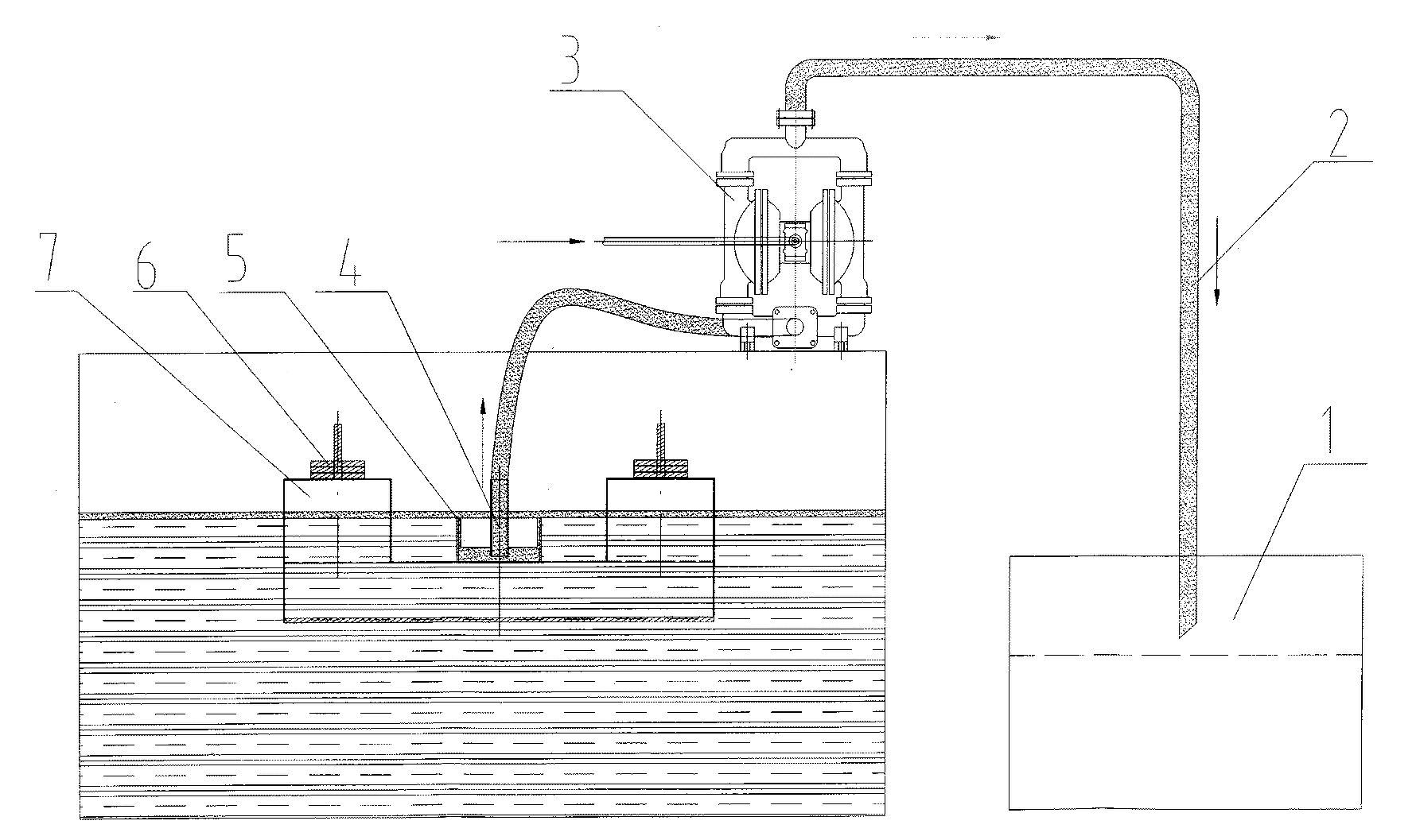
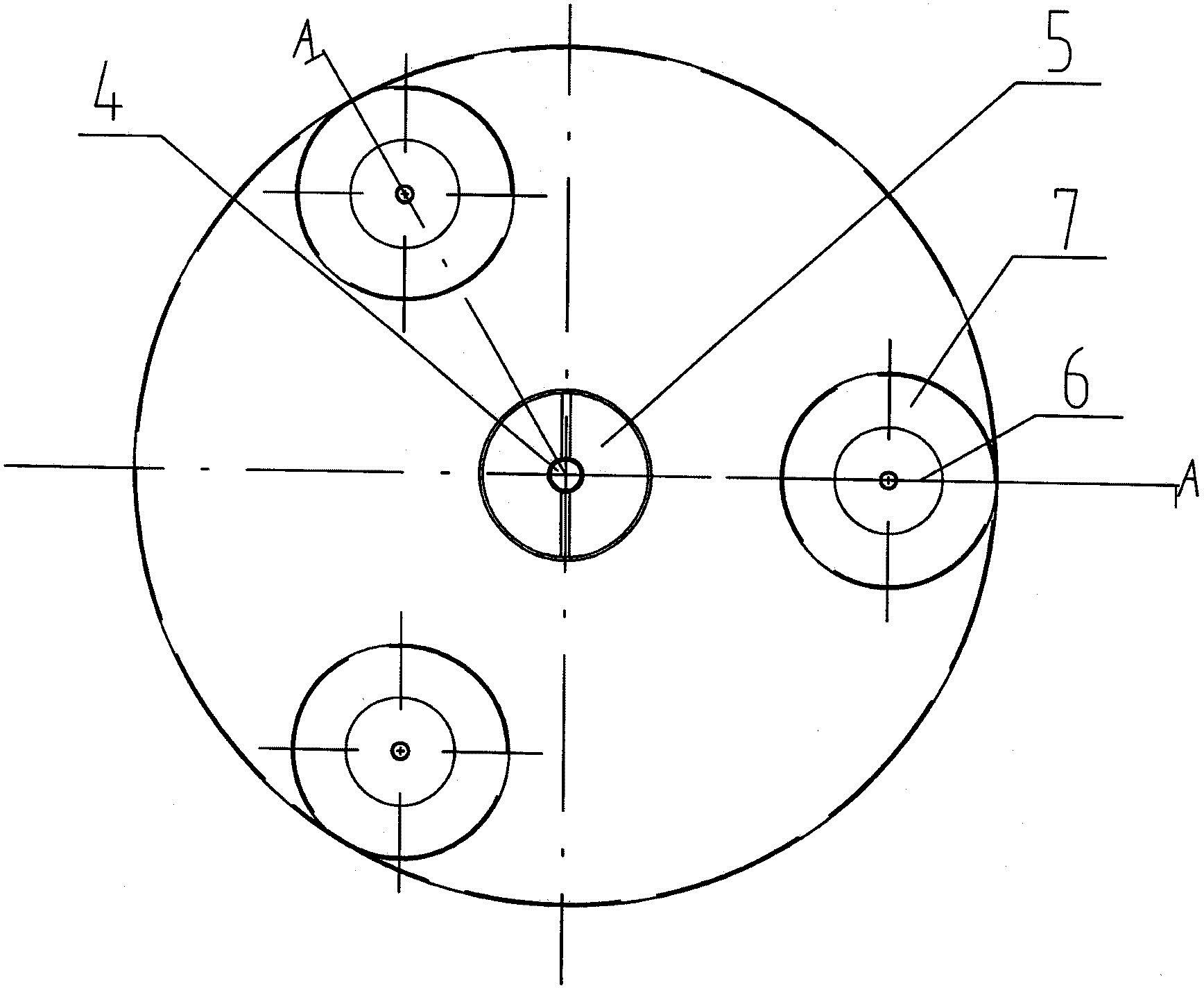
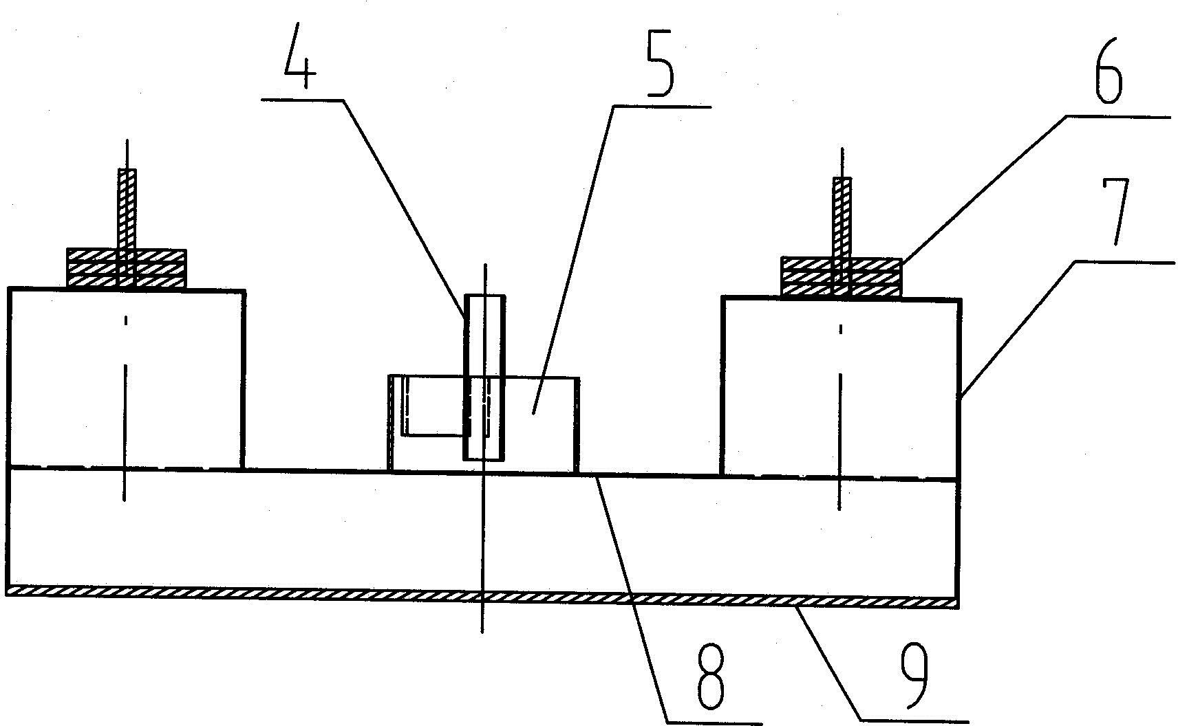
[0010] An oil slick absorber such as figure 1 , figure 2 , image 3 As shown, the absorber box is formed by the bottom plate 9 and the upper sealing plate 8 through the closed periphery, and the counterweight support 7 is evenly distributed on the surface of the upper sealing plate 8 of the box along the outer edge of the upper sealing plate 8. The counterweight 6 is installed on the counterweight support 7, and the upper open oil sump 5 is arranged at the center of the sealing plate 8 on the box body, and the upright sewage pipe 4 is fixed on the center of the oil sump 5 through a bracket. There is a channel between the lower end of 4 and the upper sealing plate 8 of the box body, the height of the top surface of the oil collecting tank 5 is lower than that of the counterweight support 7, and the upper opening of the sewage pipe 4 is connected with a pneumatic diaphragm pump through a hose 3, the outlet of the pneumatic diaphragm pump 3 leads to the sewage tank 1 through t...
PUM
 Abstract
Description
Claims
Application Information
 - R&D
- Intellectual Property
- Life Sciences
- Materials
- Tech Scout
- Unparalleled Data Quality
- Higher Quality Content
- 60% Fewer Hallucinations
Browse by: Latest US Patents, China's latest patents, Technical Efficacy Thesaurus, Application Domain, Technology Topic, Popular Technical Reports.
© 2025 PatSnap. All rights reserved.Legal|Privacy policy|Modern Slavery Act Transparency Statement|Sitemap|About US| Contact US: help@patsnap.com


