
Complete processing equipment of coal gas expanded perlite

A technology of expanded perlite and processing equipment, which is applied in the direction of lighting and heating equipment, waste heat treatment, furnace components, etc., can solve the problems of dust collector pipe loss, burn through and loss in less than a week, and achieve significant economy Benefits and social benefits, reduction of combustion, effects of solving waste

Active Publication Date: 2012-07-11
信阳市四通机械制造有限公司
View PDF3 Cites 9 Cited by
  • Summary
  • Abstract
  • Description
  • Claims
  • Application Information

AI Technical Summary

Problems solved by technology

According to calculations, the preheating furnace consumes about 30-40% of the total gas volume, and the expansion furnace consumes about 60-70% of the gas volume. The vitrified beads are wasted on the way to the silo; the wasted heat energy is mainly concentrated in two parts, one is the water tank outside the discharge pipe, and the other is the loss of dust collectors and pipelines along the way
[0003] If the traditional discharge pipe is not cooled by water, even if it uses a steel plate with a thickness of 15 mm, it will be burned through in a high temperature environment of nearly 1000 degrees Celsius after less than a week of use. Therefore, the cooling water tank is a traditional coal gas expansion furnace. An essential part; however, the high heat exchange performance of water determines that a large amount of heat energy will inevitably be exchanged by the circulating water in the cooling water tank. Except for a very small part of the hot water in the cooling water tank, which is used for workers' showers, The rest are lost for nothing

Method used


Image

  • Complete processing equipment of coal gas expanded perlite
  • Complete processing equipment of coal gas expanded perlite

Examples


Embodiment Construction

[0013] The technical solutions of the present invention will be described in further detail below through specific implementation methods.

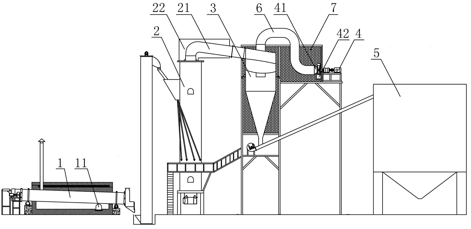
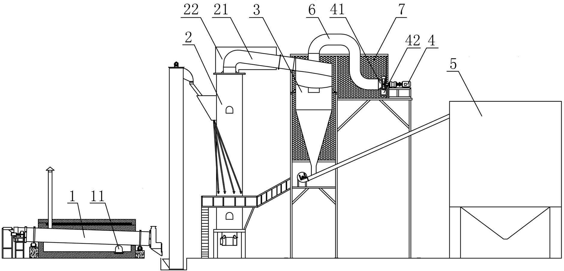
[0014] Such as figure 1 As shown, a complete set of processing equipment for coal-gas expanded perlite, which includes a coal-gas device, a preheating furnace 1, an expansion furnace 2, a cyclone dust collector 3, a high-temperature induced draft fan 4, a silo 5, and a high-temperature induced draft pipe 6 and a high-temperature discharge pipe 21; wherein, the preheating furnace 1 is provided with a high-temperature hot air inlet 11, and the high-temperature hot air inlet 11 is the existing gas combustion port of the preheating furnace 1; one end of the high-temperature discharge pipe 21 communicates with the The discharge port of the expansion furnace 2, the other end of the high-temperature discharge pipe 21 is connected to the feed port of the cyclone dust collector 3, and one end of the high-temperature induction pipe 6 is connected t...


PUM


Abstract

The invention provides complete processing equipment of coal gas expanded perlite, comprising a coal gas device, a preheating furnace, an expansion furnace, a cyclone dust collector, a material bin, a high-temperature induced-draft fan, a high-temperature discharging pipe and a high-temperature induced-draft pipe, wherein the preheating furnace is provided with a high-temperature hot-air inlet; one end of the high-temperature discharging pipe is communicated with a discharging port of the expansion furnace, and the other end of the high-temperature discharging pipe is communicated with a feeding port of the cyclone dust collector; one end of the high-temperature induced-draft pipe is communicated with the top part of the cyclone dust collector, and the other end of the high-temperature induced-draft pipe is communicated with an air inlet of the high-temperature induced-draft fan; and an air outlet of the high-temperature induced-draft fan is communicated with the high-temperature hot air inlet. The complete processing equipment has the advantages that high-temperature hot air in the cyclone dust collector is introduced to the preheating furnace for preheating ore sand by the high-temperature induced-draft fan, so that not only is the burning amount of coal gas in the preheating furnace reduced, but also the problem that the energy is wasted for nothing is solved.

Description

technical field [0001] The invention relates to the field of industrial heating furnaces, in particular to a complete set of processing equipment for coal-gas expanded perlite. Background technique [0002] The traditional coal-to-gas expansion furnace process requires two channels of gas, one for the preheating furnace to preheat the ore, and the other for the expansion furnace to expand the preheated ore into vitrified bead products. According to calculations, the preheating furnace consumes about 30-40% of the total gas volume, and the expansion furnace consumes about 60-70% of the gas volume. The vitrified beads are wasted on the way to the silo; the wasted heat energy is mainly concentrated in two parts, one is the water tank outside the discharge pipe, and the other is the loss of the dust collector and the pipeline along the way. [0003] If the traditional discharge pipe is not cooled by water, even if it uses a steel plate with a thickness of 15 mm, it will be burn...

Claims


Application Information

Patent Timeline
Patent Type & Authority Applications(China)
IPC IPC(8): C04B20/06F27D17/00
Inventor 徐正明马国伟贾志伟王元领魏泽斌程志明
Owner 信阳市四通机械制造有限公司
Learn More