
Turbocharger

A technology of vortex supercharging and annular shell, which is applied in the direction of blade support components, engine components, machines/engines, etc., which can solve the problems of quality reduction, engine vacuum degree drop, engine cylinder vacuum degree drop, etc., to achieve full replenishment, improve The effect of intake capacity and efficiency

Inactive Publication Date: 2012-07-11
姜国清
View PDF0 Cites 0 Cited by
  • Summary
  • Abstract
  • Description
  • Claims
  • Application Information

AI Technical Summary

Problems solved by technology

[0003] 1. Insufficient air intake caused by the resistance of the air filter element;
[0004] 2. Insufficient air intake caused by the resistance of the air duct;
[0005] 3. Insufficient air intake caused by engine exhaust resistance;
[0006] 4. When the engine piston reaches the top dead center, there is still a part of the vacant area inside the cylinder head that has not been eliminated, and a 100% vacuum state is not completely formed in the cylinder, resulting in a decrease in the vacuum degree in the engine cylinder and a decrease in the suction force. lead to insufficient air intake;
[0007] 5. The air leakage caused by the incomplete sealing of the intake and exhaust valves in the engine and the expansion gap that must be reserved for the sealing piston ring itself cause the vacuum degree of the engine to drop, resulting in insufficient intake air;
Air expands and loses mass as altitude increases
The air quality of 1 cubic meter in the high altitude area is actually less than the air quality of 1 cubic meter in the 0 altitude area. The flow is used to command the fuel supply system to supply the engine fuel according to the original design standard, but the actual air entering is less, resulting in insufficient air intake

Method used


Image

  • Turbocharger
  • Turbocharger
  • Turbocharger

Examples


Embodiment Construction

[0025] The object of the present invention is to provide a turbocharger device to solve the problem of insufficient air intake in the engine; another object of the present invention is to provide an engine comprising the above turbocharger device, the engine air supply is very sufficient.

[0026] In order to make the purpose, technical solutions and advantages of the embodiments of the present invention clearer, the technical solutions in the embodiments of the present invention will be clearly and completely described below in conjunction with the drawings in the embodiments of the present invention. Obviously, the described embodiments It is a part of embodiments of the present invention, but not all embodiments. Based on the embodiments of the present invention, all other embodiments obtained by persons of ordinary skill in the art without making creative efforts belong to the protection scope of the present invention.

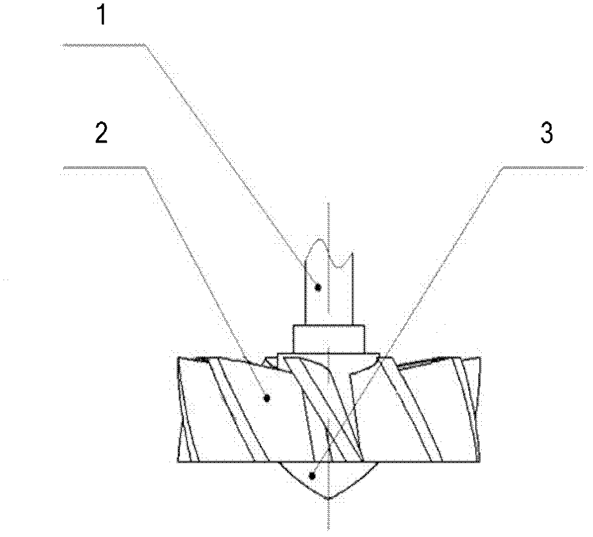
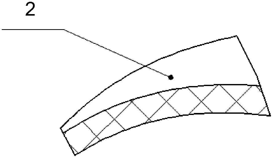
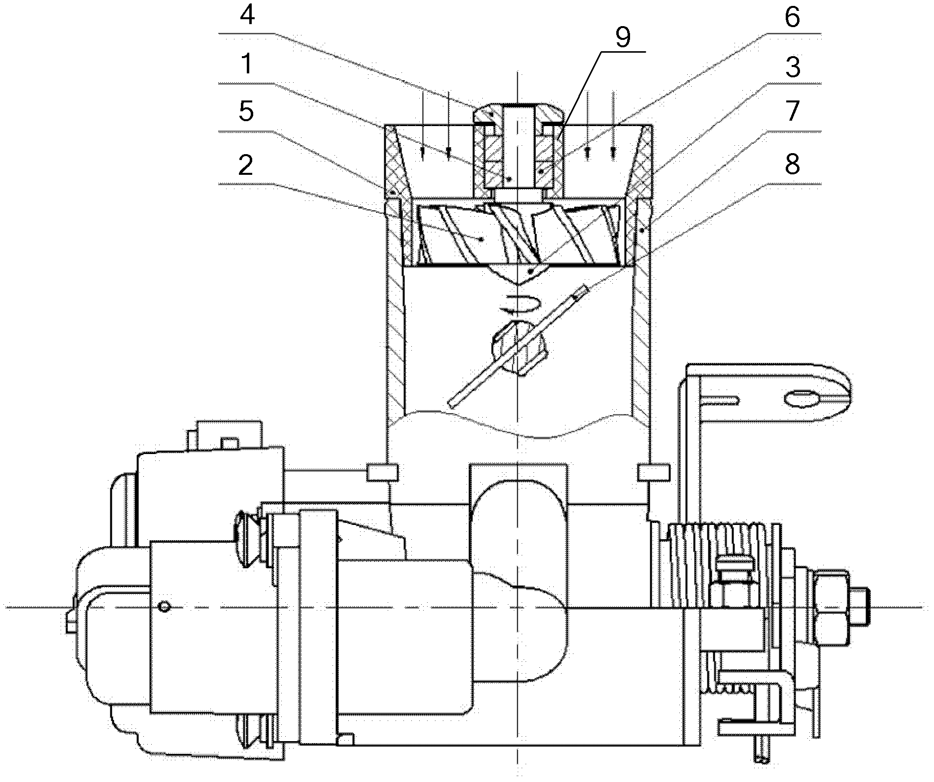
[0027] Please refer to Figure 1 to Figure 3 , fig...


PUM


Abstract

The invention discloses a turbocharger, which is used for increasing air inlet quantity of an engine. The turbocharger is characterized by comprising an annular shell, an annular inner wall, a bearing, an impeller rotating shaft and arc-shaped blades, the annular inner wall is fixed in the annular shell via reinforcing ribs, a gap is formed between the annular inner wall and the annular shell, the bearing is placed in the annular inner wall, the impeller rotating shaft matches with the bearing, a set included angle is formed between the extension direction of each arc-shaped blade and the axis of the impeller rotating shaft, and the arc-shaped blades are mounted on the impeller rotating shaft. The turbocharger generates airflow with additional lift force kinetic energy, so that airflow inlet speed of the engine is comprehensively increased to increase the air inlet quantity within unit time, air inlet ability and efficiency are greatly improved, and sufficient supply of air in the engine is realized.

Description

technical field [0001] The invention relates to the technical field of turbocharging, in particular to a turbocharging device. Background technique [0002] The theoretical air-fuel ratio of a car engine, that is, the ratio of air and fuel required to achieve complete combustion is 14.5:1, and the best air-fuel ratio is 15.0:1. At this time, the mixture is in the best state of lean combustion, and the fuel can be Complete combustion, the engine can reach the maximum power calibrated by the original design at this time. However, since the air required for the natural intake of the engine is completely dependent on the negative pressure generated when the piston descends, it is restricted by many factors and basically cannot Reaching the best air-fuel ratio state of 15.0:1, under the natural air intake state of the engine, the general air intake can only reach 65% to 90% of the design requirement, so the engine can only emit 65% to 90% of the original design power. The aforem...

Claims


Application Information

Patent Timeline
IPC IPC(8): F02B33/00F01D5/02F01D25/16F01D25/24
Inventor 姜国清李建吕青山
Owner 姜国清
Learn More