

Household gas burner
A gas burner and gas technology, applied in the directions of burners, gas fuel burners, combustion methods, etc., can solve the problems of inconvenient installation, repair, maintenance, dismantling and cleaning of cooking appliances, increase the hidden danger of gas combustion safety, and low gas combustion efficiency, etc. Achieve the effect of avoiding yellow flame phenomenon, improving utilization rate and full combustion
Active Publication Date: 2011-01-05
HANGZHOU DE&E ELECTRICAL CO LTD
View PDF4 Cites 0 Cited by
- Summary
- Abstract
- Description
- Claims
- Application Information
AI Technical Summary
Problems solved by technology
In this patent, the injection tube assembly is fixed under the gas mixing chamber. Due to the large number of injection tube assemblies, the workload of the burner is relatively large during installation, and because the injection tube assembly is used to transport the external gas to the In the burner, once the number of independent components in the ejector tube assembly increases, the cumulative error when the components are connected to each other is large, which increases the safety hazard during gas combustion; the inner ring gas mixing chamber and the outer ring in the burner The gas mixing chamber has only one simple cavity, and it is difficult for gas and air to mix evenly in such a gas mixing chamber, which makes the gas burn unevenly and affects the performance of the entire cooker
There is also a Chinese patent with an announcement date of July 5, 2006 and an announcement number of 200520102504.0, which discloses a domestic gas cooker with an upper-inlet double-jet burner; an announcement date of March 26, 2003, and an announcement number of 02201626.0 In the Chinese patents, a gas stove with an internal spacer is disclosed. The burners in these patents have complicated structures, and the combustion efficiency of the gas is low. cause greater inconvenience
To sum up, at present there is no household gas burner with simple structure, good processing precision, small accumulated error during assembly, uniform flame when gas is burned, high gas utilization rate, and no yellow flame phenomenon, which gives people The use of gas cookers has brought some inconvenience, especially in China, where the utilization rate of gas cookers is high, so it is of great practical significance to seek a gas burner with excellent performance.
Method used
View moreImage
Smart ImageViewing Examples

Examples
Embodiment
Login to View More PUM
 Abstract
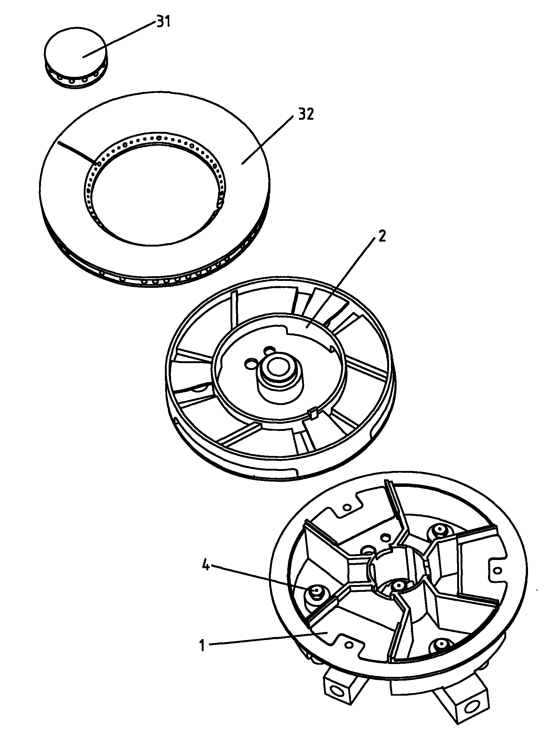
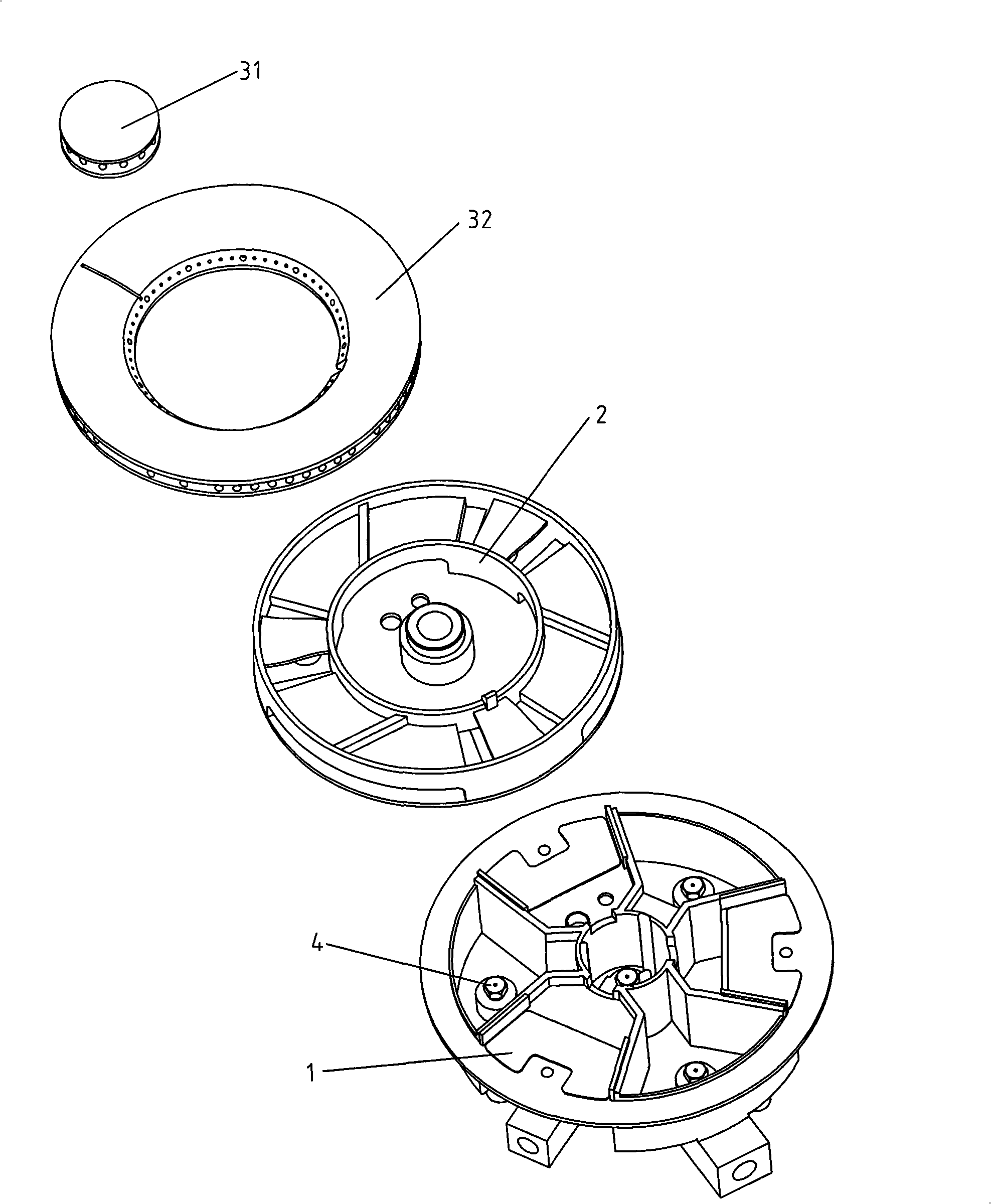
The invention discloses a household gas burner, belonging to the part in the household gas kitchen range. The present household gas burner has the complex structure, poor processing precision and big accumulative error in assembling. The household gas burner comprises a nozzle, a gas distributing device, a gas mixing device and a fire lid, and characterized in that the gas distributing device andthe gas mixing device are all the integrated structure, wherein the gas distributing device comprises a gas supplying pipe and a distributing chamber, a primary air inlet open is arranged on the distributing chamber, the nozzle is fixed on the orifice of the gas supplying pipe in the distributing chamber; the gas mixing device comprises a mixing pipe, a mixing chamber, a buffer baffle plate and asecondary air inlet slot, the mixing chamber is matched with the distributing chamber, the buffer baffle plate is arranged above the orifice of the mixing pipe in the mixing chamber, the secondary air inlet slot is arranged at the side surface of the gas mixing device. The gas distributing device and the gas mixing device in the invention have no accumulative error in assembling, simple assembling and safe and reliable use.
Description
Household Gas Burner technical field The invention relates to a gas burner, in particular to a household gas burner, which is mainly installed in a household gas cooker and belongs to a part of the household gas cooker. Background technique At present, most of the existing burners installed in household gas cookers adopt two types: a bottom air intake type and an upward air intake type. Among them, most of the bottom air intake burners use vertical or horizontal ejectors, because the embedded part is a sealed structure, and an air inlet must be set on the cooker panel to allow air to enter the interior of the shell to provide the primary air required for the burner to burn. ; If it is a double-jet burner, it is also necessary to set a channel on the cooker panel to supplement the secondary air required for gas combustion in the inner ring fire hole, which adds a certain degree of difficulty to the overall design of the cooker and the overall design of the kitchen. And it ...
Claims
Login to View More Application Information
Patent Timeline
 Patent Type & AuthorityPatents(China)
IPC IPC(8): F23D14/02F23D14/46F23D14/60F23D14/64
Inventor高利见黄关德张向君
OwnerHANGZHOU DE&E ELECTRICAL CO LTD