

Coal and gangue separation device
A coal gangue separation and sieve bar technology, which is applied in wet separation, filtration separation, solid separation, etc., can solve the problems of high difficulty in force control and scattered thrust, and achieve a compact structure, reduced floor space, and reduced control difficulty. Effect
- Summary
- Abstract
- Description
- Claims
- Application Information
AI Technical Summary
Problems solved by technology
Method used
Image

Examples
Embodiment 1
[0037] Embodiment 1: A high-precision gangue identification system
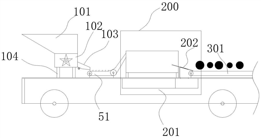
[0038] refer to figure 1 , this embodiment proposes a high-precision gangue identification system, including: a base 1 , a cloth queuing device 100 and a gangue identification device 200 .
[0039] The fabric queuing device 100 includes: a hopper 101 , a star feeder 102 and a first support foot 104 .
[0040] The star feeder 102 is installed on the base 1 through the first supporting foot 104 , and the feeding hopper 101 is arranged on the star feeder 102 . The top of the feeding hopper 101 is open, and the bottom is provided with a monolithic material outlet and communicated with the mineral material inlet of the star feeder 102 . In this way, the mineral material fed into the hopper 101 is discharged through the star feeder 102, realizing the intermittent and uniform discharge of the mineral material. During specific implementation, the feeding hopper 101 can also be set as an upper-wide loading structur...
Embodiment 2
[0055] Embodiment 2: A coal gangue identification device
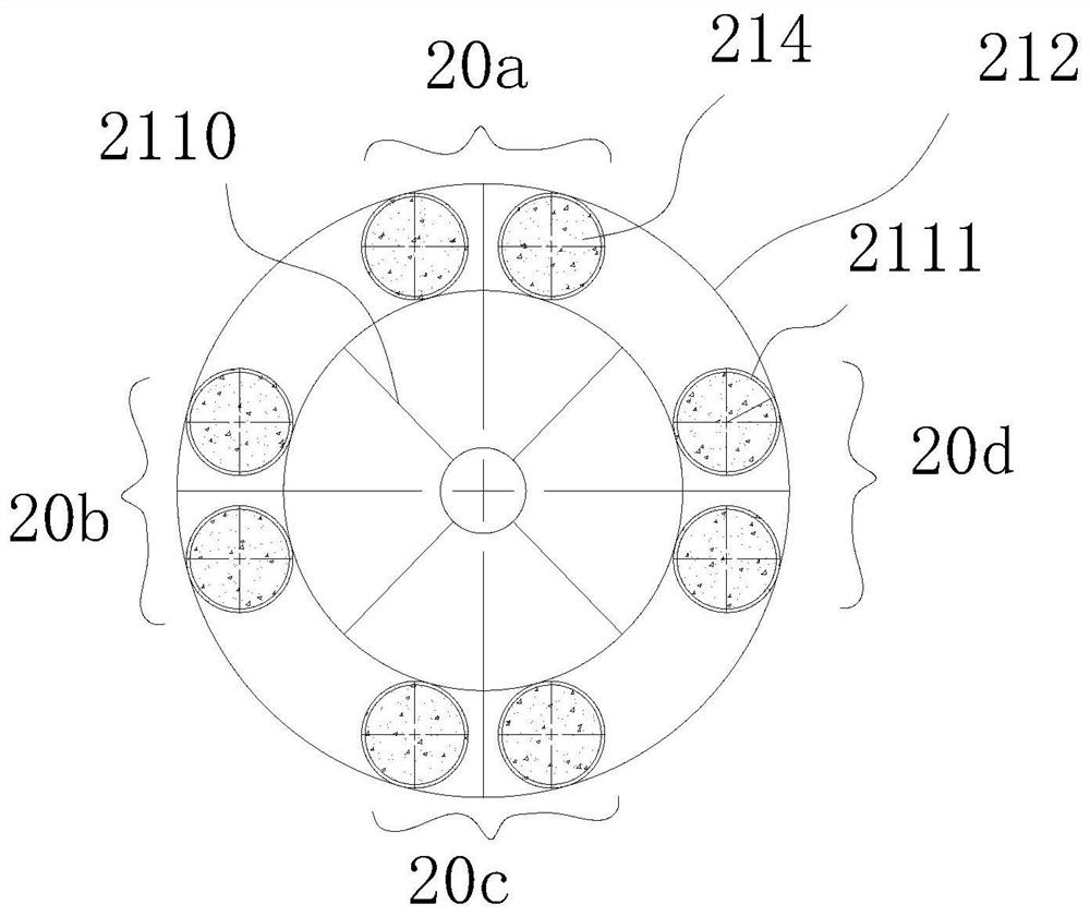
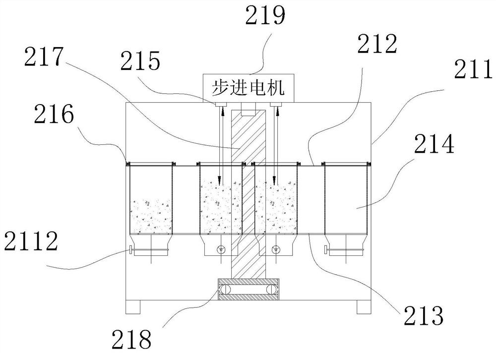
[0056] refer to figure 2 , image 3 , this embodiment provides a structure of the gangue identification device in Embodiment 1.
[0057] In this embodiment, the rotating support frame includes a vertically arranged first rotating shaft 217 and a loading bracket connected to the first rotating shaft 217 and rotating synchronously with the first rotating shaft 217 . Specifically, in this embodiment, the first rotating shaft 217 is connected with a first motor 219 for driving its rotation. The bottom end of the first rotating shaft 217 is also provided with an axial thrust bearing 218 to ensure its stable rotation. In this embodiment, a first cylinder 211 is further provided on the base 1 , and the top of the first cylinder 211 is open. The first rotating shaft 217 is disposed in the first cylinder 211 through an axial thrust bearing 218 , and the loading units are also located in the first cylinder 211 . In this wa...
Embodiment 3
[0064] Embodiment 3: A kind of wheel-type gangue identification device
[0065] This embodiment provides another structure of the gangue identification device in Embodiment 1.
[0066] refer to Figure 7 to Figure 11 , in this embodiment, the rotating support frame includes: a second rotating shaft 225 . The second rotating shaft 225 is horizontally installed on the base 1 and is connected with a second motor 229 for driving it to rotate. The second weighing cylinder 227 as a loading unit is arranged on the second rotating shaft 225 and is evenly distributed along its rotating circumferential direction, and the second weighing cylinder 227 and the second rotating shaft 225 rotate synchronously. The opening direction of the second weighing cylinder 227 is consistent with the rotation direction of the second rotating shaft 225 , and the second weighing cylinder 227 located in the water injection area 20 a is located in the circulating water tank 201 . In this way, with the ro...
PUM
 Abstract
Description
Claims
Application Information