Oil pump rotor deburring device

A technology for deburring and rotors, which is used in grinding machines, grinding machine parts, grinding/polishing equipment, etc. It can solve problems such as poor deburring effect, poor deburring effect, and hidden safety hazards, and achieve high efficiency, Improve clamping effect and prevent offset effect

Active Publication Date: 2018-05-08
ZHEJIANG UNIV CITY COLLEGE
View PDF7 Cites 2 Cited by
  • Summary
  • Abstract
  • Description
  • Claims
  • Application Information

AI Technical Summary

Problems solved by technology

The working process of the existing deburring device is to manually feed the material first, fix the oil pump rotor, then open the polishing mechanism for deburring treatment, and manually take it out after the treatment is completed. The whole process is not only inefficient, but also has problems certain security risks
At the same time, due to the different thickness of different workpieces, it is necessary to frequently adjust the height of the polished parts manually to adapt to the thickness of the workpiece. Due to errors in manual adjustment, this will lead to poor deburring effect
Therefore, the existing technology has the problem of low efficiency and poor deburring effect

Method used


Image

  • Oil pump rotor deburring device
  • Oil pump rotor deburring device
  • Oil pump rotor deburring device

Examples


Embodiment Construction

[0026] The present invention will be further described below in conjunction with the accompanying drawings and embodiments, but not as a basis for limiting the present invention.

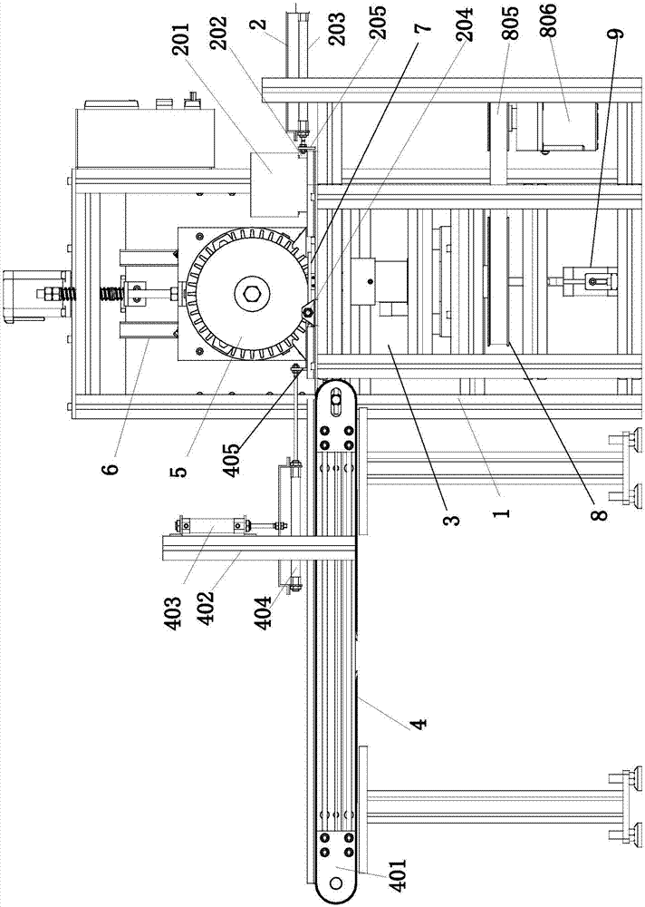
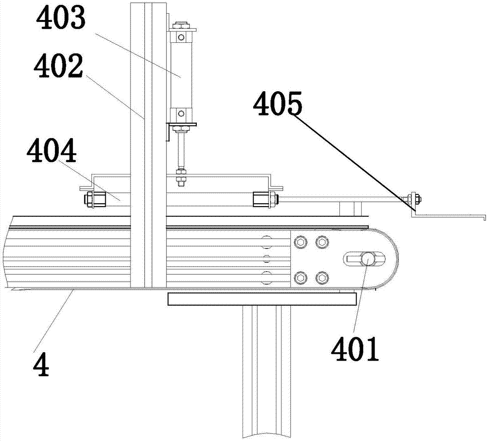
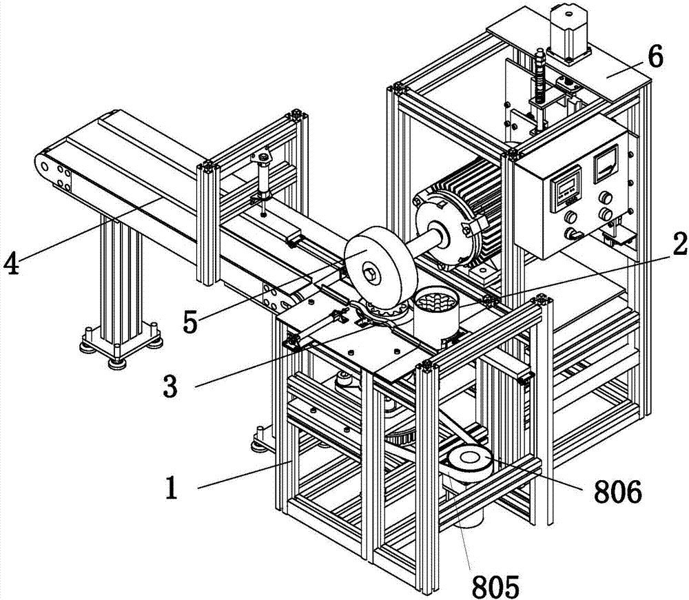
[0027] Example. An oil pump rotor deburring device, constituted as Figure 1 to Figure 8 As shown, it includes a frame 1, and the frame 1 is sequentially provided with a feeding part 2, a clamping part 3 and a discharging part 4 along the discharge direction, and a grinding head 5 is arranged above the clamping part 3, and the grinding head 5 is connected to There is a grinding head part 6 positioned at the side of the clamping part 3; the feeding part 2 includes an upper material bin 201 arranged at one end of the frame 1, and the lower part of the upper material bin 201 is provided with a push port 202, and both sides of the upper material bin 201 A push-in cylinder 203 and a limit cylinder 204 are respectively provided, and the extension end of the push-in cylinder 203 is provided with a push pl...


PUM


Abstract

The invention discloses an oil pump rotor deburring device which comprises a rack (1); a charging component (2), a clamping component (3) and a discharging component (4) are sequentially arranged on the rack (1); a grinding head (5) is arranged above the clamping component (3), and is connected with a grinding head component (6) located on the side surface of the clamping component (3); the charging component (2) comprises a charging bin (201) arranged at one end of the rack (1); a push-in port (202) is formed in the lower part of the charging bin (201); a push-in air cylinder (203) and a limiting air cylinder (204) are arranged on the two sides of the charging bin (201) correspondingly; a push plate (205) corresponding to the push-in port (202) is arranged at the protruding end of the push-in air cylinder (203); a limiting rod (206) is arranged at the protruding end of the limiting air cylinder (204); and the limiting rod (206) is located at the discharging end of the clamping component (3). The oil pump rotor deburring device has the characteristics that the burr treatment efficiency can be improved and the deburring effect can be improved.

Description

technical field [0001] The invention relates to a surface polishing device for rotor workpieces, in particular to a deburring device for an oil pump rotor. Background technique [0002] After the production of the oil pump rotor is completed, the surface roughness is relatively high, and a polishing mechanism is required for polishing and deburring. The working process of the existing deburring device is to manually feed the material first, fix the oil pump rotor, then open the polishing mechanism for deburring treatment, and manually take it out after the treatment is completed. The whole process is not only inefficient, but also has problems Certain security risks. At the same time, due to the different thicknesses of different workpieces, it is necessary to frequently adjust the height of the polished parts manually to adapt to the thickness of the workpieces. Due to errors in manual adjustments, the effect of deburring will be poor. Therefore, the existing technology h...

Claims


Application Information

Patent Timeline
Patent Type & Authority Applications(China)
IPC IPC(8): B24B9/04B24B41/00B24B41/06
CPCB24B9/04B24B41/005B24B41/007B24B41/06
Inventor 张俊
Owner ZHEJIANG UNIV CITY COLLEGE
Why Eureka
Try Eureka