Spring seat mounts for shock absorbers

A technology of fixing devices and spring seats, applied in the direction of shock absorbers, springs, spring/shock absorber design features, etc., can solve problems such as failure to meet safety requirements, loss of car control, traffic accidents, etc.

Inactive Publication Date: 2015-12-02
ZF FRIEDRICHSHAFEN AG
View PDF7 Cites 0 Cited by
  • Summary
  • Abstract
  • Description
  • Claims
  • Application Information

AI Technical Summary

Problems solved by technology

Through the changed spring force, the driving behavior of the vehicle is also changed, which may lead to a loss of control of the car and thus a traffic accident
In this view, the described structures may not meet the high safety requirements currently in force

Method used


Image

  • Spring seat mounts for shock absorbers
  • Spring seat mounts for shock absorbers
  • Spring seat mounts for shock absorbers

Examples


Embodiment Construction

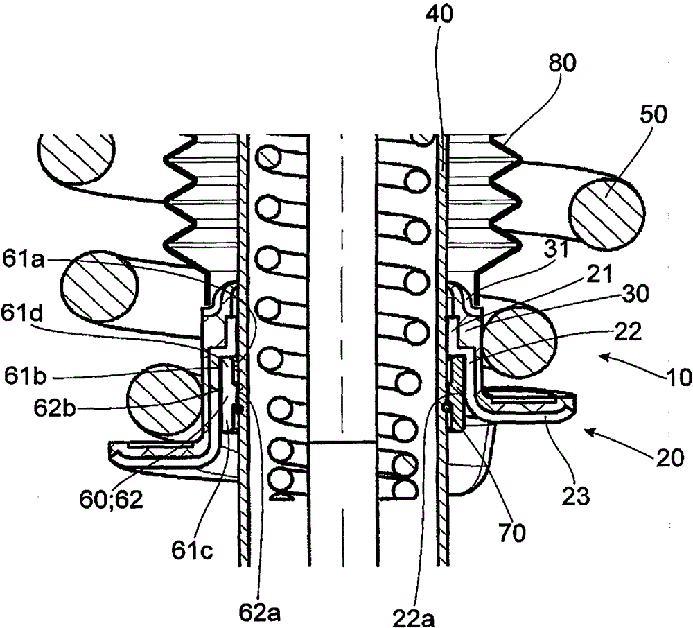
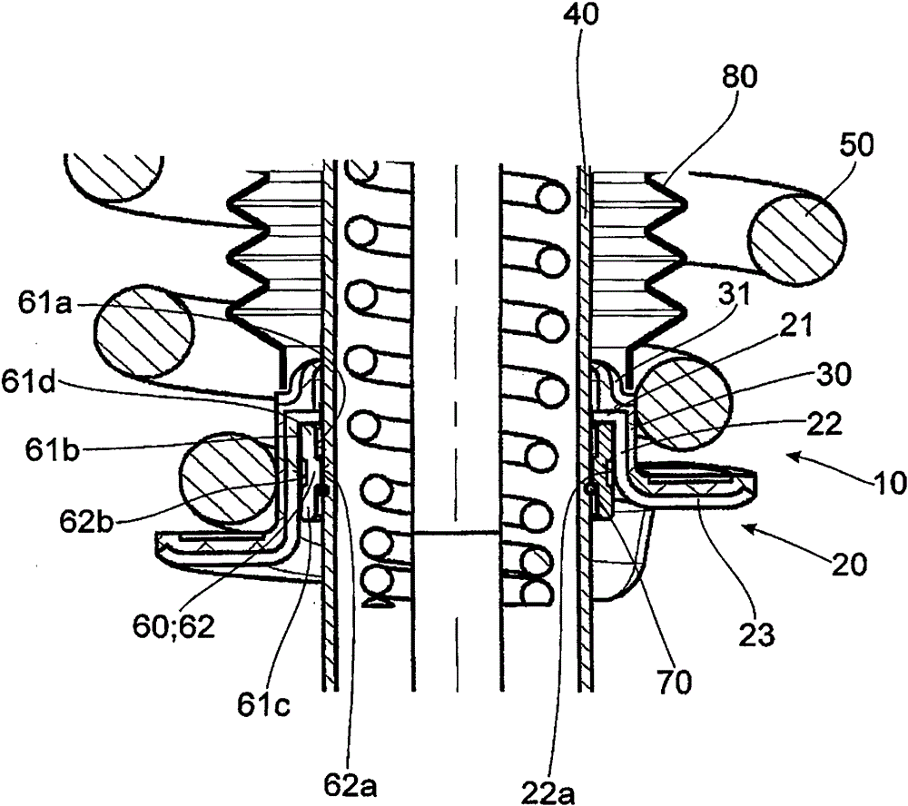
[0027] figure 1 A spring seat fixing device 10 for a shock absorber according to the present invention is shown. The spring seat fixing device includes a spring seat 20 having a contact section 21 that surrounds the vibration damping tube 40 in the circumferential direction. In addition, the spring seat 20 further has a receiving section 22 spaced from the contact section 21 in the axial direction and in the radial direction, and a support section 23 spaced from the contact section 21 in the axial direction. The support section 23 here supports the suspension spring 50 in the axial direction via its substantially disk-shaped radial extension. In addition, in figure 1 as well as figure 2 Shown therein is an isolation element 60 implemented as a one-piece, which also encloses the damping tube 40 and is arranged inside the receiving section 22 of the spring seat 20. figure 2 with Figure 5 The insulation element 60 shown is embodied as a thin sheet metal molded part.

[0028] in ...


PUM


Abstract

The arrangement (10) has a spacer element (60) with a middle section (62) axially arranged between outer sections (61c, 61d) of the spacer element. The middle section partially contacts a damper tube (40) with its radial inner surface (62a). A fuse element (70) encloses the damper tube, and is radially arranged between the damper tube and a radial inner surface (61a) of one of the outer sections of the spacer element. The arrangement is securely arranged against axial loading, and the spacer element is designed as sheet shaped-metal.

Description

Technical field [0001] The invention relates to a spring seat fixing device for a shock absorber. Background technique [0002] Spring seat fixing devices for shock absorbers of the preceding type have long been known in the automotive industry. [0003] The current requirements for the comfort of motor vehicles have greatly increased. In addition, the solution must currently be highly variable and low-cost and must meet high safety standards. [0004] In order to meet the comfort requirements, the various automotive components must be extremely accurately coordinated with each other. [0005] For example, on cars with the same structural series but with different degrees of motorization, suspension springs need to be used, whose spring force can meet the comfort requirements of different car models. This can be achieved by using different suspension springs. But this will increase production costs. Another possibility to change the spring force is to preload the suspension spring...

Claims


Application Information

Patent Timeline
Patent Type & Authority Patents(China)
IPC IPC(8): F16F9/32B60G15/02
CPCF16F9/3235B60G15/063B60G2202/30B60G2202/312B60G2204/1242F16F2230/24
Inventor T·普夫劳姆G·汉德克F·卡尔
Owner ZF FRIEDRICHSHAFEN AG
Why Eureka
Try Eureka