Magnetorheological fluid transmission device with variable power

A magnetorheological fluid and transmission technology, applied in the transmission, friction transmission, belt/chain/gear, etc., can solve the problem that the reliability and energy saving of the magnetorheological fluid transmission have not been considered and designed, and the transmission has not been considered. Power change, magnetorheological fluid is easy to wear and other problems, to expand the scope of use and occasions, avoid the increase of working gaps, and save energy.

Inactive Publication Date: 2012-07-11
CHINA UNIV OF MINING & TECH
View PDF9 Cites 12 Cited by
  • Summary
  • Abstract
  • Description
  • Claims
  • Application Information

AI Technical Summary

Problems solved by technology

However, these patents still have some common defects of current magnetorheological fluid transmission: magnetorheological fluid is easy to wear after long-term use, and its transmission performance will be reduced
; The magnetorheological fluid transmission does not consider the occasion of the transmission power change, but only adjusts the torque by adjusting the current; the reliability and energy saving of the magnetorheological fluid transmission are not considered and designed. When the magnetorheological fluid transmission is applied to special The transmission of occasions, such as mines and other places with high safety, is restricted in its use.

Method used


Image

  • Magnetorheological fluid transmission device with variable power
  • Magnetorheological fluid transmission device with variable power

Examples


Embodiment Construction

[0010] The present invention will be further described below in conjunction with accompanying drawing.

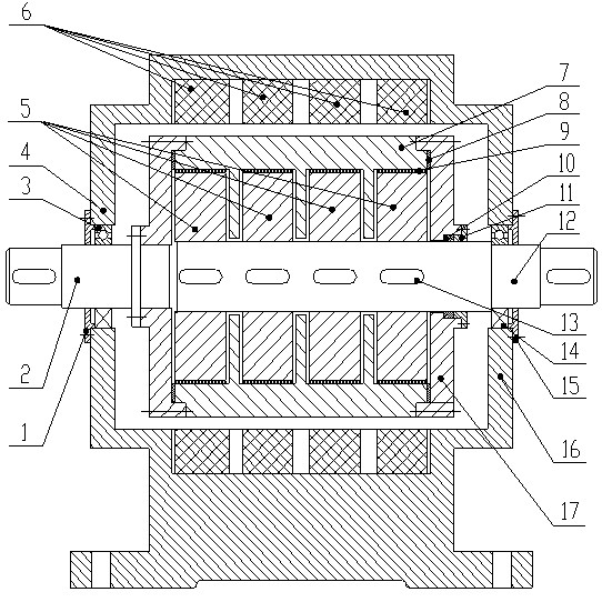
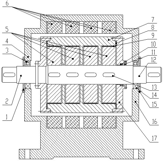
[0011] like figure 1 As shown, a magneto-rheological fluid transmission device with variable power includes a driving shaft 2, an upper casing 4, a driven rotor 5, an electromagnetic coil 6, a driving drum 7, a driven shaft 12 and a lower casing 16, The transmission box consists of an upper box 4 and a lower box 16. The electromagnetic coil 6 is fixedly installed inside the transmission box. The driving shaft 2 passes through the left bearing end cover 1 and the driving bearing 3, and the driving shaft 3 supports the driving One end of the shaft 2 and the other end of the driving shaft 2 are connected to the end surface 17 of the driving drum through bolts, and the driven shaft 12 passes through the driving drum 7 and the end cover 11 and is sealed with an "O"-shaped sealing ring 10, and then passes through the box installed in the box. The driven bearing 14 on the body an...


PUM


Abstract

The invention discloses a magnetorheological fluid transmission device with variable power, belonging to the technical field of transmission devices. The magnetorheological fluid transmission device comprises a driving shaft, an upper box body, a driven rotor, an electromagnetic coil, a driving drum, a driven shaft and a lower box body, wherein the driving shaft penetrates through an end cover of a left bearing and a driving bearing and is connected with the end surface of the driving drum, the driven shaft penetrates through the driving drum and the end cover and is supported by a driven bearing, the driving drum has a partition structure, a plurality of gaps are partitioned in the driving drum, the driven rotor is positioned in the gaps partitioned in the driving drum and is connected with the driven shaft by a flat key, a gap is left between the inner wall of the driving drum and the outer wall of the driven rotor, magnetorheological fluid is filled in the gaps, and the installation position of the electromagnetic coil corresponds to the installation position of the driven rotor. The magnetorheological fluid transmission device has the beneficial effects that one or more driven motors is/are used according to the need of actual power transfer, the use range and occasions of the transmission device are enlarged, the driven motors can be used alternatively so as to reduce abrasion of surfaces of the driving and driven rotors, and the service life of the transmission device is prolonged.

Description

technical field [0001] The invention relates to a magneto-rheological fluid transmission device with variable power, belonging to the technical field of transmission devices. Background technique [0002] The general machine is composed of four parts: the driving part, the working part, the transmission part and the control part. The main function of the transmission part is to transmit the power and motion of the prime mover to the working part, and the transmission device is the core of the transmission part. Traditional mechanical transmission devices have disadvantages such as impact, loud noise, and difficulty in shifting speeds. To address these shortcomings, it is necessary to conduct research on new transmission technologies. With the discovery of magnetorheological technology, there has been a transmission device for magnetorheological fluid. The transmission device of magnetorheological fluid uses a new type of intelligent material magnetorheological fluid to rea...

Claims


Application Information

Patent Timeline
Patent Type & Authority Applications(China)
IPC IPC(8): F16H15/01
Inventor 刘新华刘永志刘浩李奇刘友会刘秀梅
Owner CHINA UNIV OF MINING & TECH
Why Eureka
Try Eureka