
Light emitting device, projection device and lighting device

A light-emitting device and excitation light technology, which is applied in the field of optics, can solve the problems of large excitation light energy loss, energy loss, and low light source efficiency, and achieve the effect of solving color uniformity and luminous efficiency

Active Publication Date: 2012-07-11
APPOTRONICS CORP LTD
View PDF12 Cites 68 Cited by
  • Summary
  • Abstract
  • Description
  • Claims
  • Application Information

AI Technical Summary

Problems solved by technology

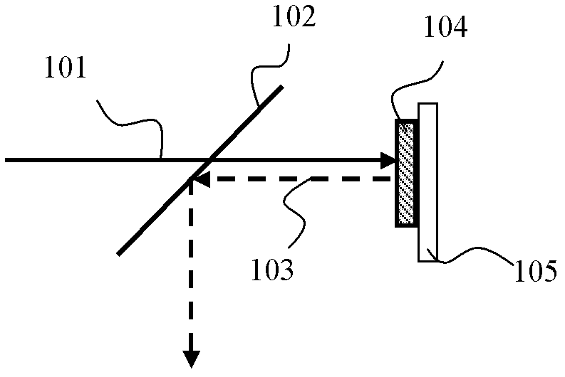
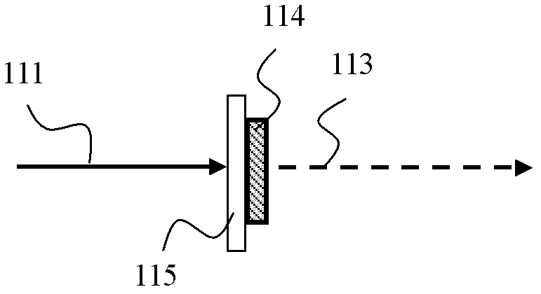
[0010] However, the problem of adding light-scattering materials is that due to the increased scattering of the excitation light, a considerable part of the excitation light is directly reflected back after the excitation light is incident on the phosphor layer, and is transmitted through the spectroscopic filter 115 to form a back-facing energy loss
It is easy to understand that the more uniform the color of the outgoing light is, the more astigmatism material needs to be added, the greater the energy loss of the excitation light at the back, and the lower the efficiency of the light source

Method used


Image

  • Light emitting device, projection device and lighting device
  • Light emitting device, projection device and lighting device
  • Light emitting device, projection device and lighting device

Examples


Embodiment Construction

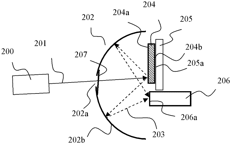
[0031] As mentioned in the background technology, in the existing light source schemes that can emit mixed light of excitation light and stimulated light, the uniformity and efficiency of the light source constitute a pair of contradictions, and the essential reason is that the addition of scattering materials causes Reflected excitation light cannot be exploited. The present invention proposes a new light source structure. A light guiding device is provided on the incident side of the wavelength conversion material layer where the excitation light is incident. The unabsorbed excitation light reflected by the material layer enters the light exit channel of the light source, thereby realizing the reuse of the wasted excitation light in the prior art, and fundamentally solving the contradiction between luminous uniformity and efficiency.

[0032] The light-emitting device of the present invention can emit uniformly mixed light of excitation light and received light with high eff...


PUM


Abstract

The invention provides a light emitting device, a projection device and a lighting device. The light emitting device comprises a wavelength conversion material layer and a light guiding device, wherein the wavelength conversion material layer with a first surface and a second surface comprises a wavelength conversion material and a scattering material, and the light guiding device is positioned on one side of the first surface of the wavelength conversion material layer and used for guiding exciting light into the first surface of the wavelength conversion material layer, and guiding stimulated light and residual exciting light to enter a light emitting channel, wherein the stimulated light is emitted by the first surface of the wavelength conversion material layer, and the residual exciting light is absorbed by the wavelength conversion material layer. By the aid of the light emitting device, the light guiding device positioned on one side of the first surface of the wavelength conversion material layer is effectively positioned can be used for effectively collecting the exciting light reflected by the wavelength conversion material layer, so that the efficiency of the light emitting device cannot be affected by the scattering material added by the scattering material, and the contradiction between color uniformity and light emitting efficiency is solved.

Description

technical field [0001] The invention relates to the field of optical technology, in particular to a light emitting device, a projection device and an illuminating device. Background technique [0002] At present, solid-state light sources have been widely used in general lighting, special lighting and projection display due to their long life and environmental protection. Among them, the white light solid-state light source has great development potential in the field of lighting. [0003] There are two main implementation methods for white light solid-state light sources. One method is to use multiple monochromatic solid-state light sources to synthesize white light, such as red, green, and blue light-emitting diodes (LED, Light Emitting Diode) are lit together to generate white light; the other One method is to use blue light to excite the yellow phosphor, and use the yellow light excited by the yellow phosphor to mix with the remaining blue light that has not been absorb...

Claims


Application Information

Patent Timeline
Patent Type & Authority Applications(China)
IPC IPC(8): F21S2/00F21V13/00G03B21/20F21V9/40
CPCF21Y2101/02F21V9/00F21Y2101/025G03B21/204G03B21/14G02B6/0001F21V9/10F21V9/45F21Y2115/10F21Y2115/30G03B21/208
Inventor 张利利许颜正
Owner APPOTRONICS CORP LTD
Learn More