Power circuit, power recovery control circuit and method

A control circuit and power recovery technology, applied in the field of power supply, can solve problems such as power supply Vout voltage cannot be established, system power failure, etc., and achieve the effect of low cost and simple solution

Active Publication Date: 2022-07-15
ZTE CORP
View PDF0 Cites 0 Cited by
  • Summary
  • Abstract
  • Description
  • Claims
  • Application Information

AI Technical Summary

Problems solved by technology

If there is no Oring circuit at the output of the power supply, then when the mains power is restored, the PWM control chip inside the power supply starts to power on and work, and the control loop of the power supply detects that the output of the power supply has a voltage (that is, the battery voltage), and it is higher than the power supply itself. If the output voltage of the power supply is high, then the PWM chip of the power supply will no longer be driven, resulting in the failure of the Vout voltage of the power supply itself to be established.
In this case, even if S1 is disconnected with a delay, the system will still be powered off for a short time because the output voltage of the power supply cannot be established immediately.

Method used


Image

  • Power circuit, power recovery control circuit and method
  • Power circuit, power recovery control circuit and method
  • Power circuit, power recovery control circuit and method

Examples


Embodiment 1

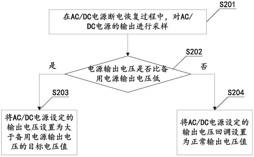
[0027] In this embodiment, the control of AC / DC power failure recovery adopts figure 2 The control process shown is implemented:

[0028] S201: sampling the output of the AC / DC power supply during the recovery process of the AC / DC power supply;

[0029] In this step, at least one of the output voltage and current of the AC / DC power supply may be sampled. And the circuits and sampling rules used for specific sampling can be flexibly set according to actual application scenarios.

[0030] S202: According to the sampling result, determine whether the output voltage of the AC / DC power supply is lower than the output voltage of the current backup power supply, if so, go to S203; otherwise, go to S204.

[0031] S203: Set the output voltage set by the AC / DC power supply to a target voltage value greater than the output voltage of the backup power supply. This ensures that the output voltage of the AC / DC power supply is higher than the voltage of the current standby power supply, ...

Embodiment 2

[0067] In order to better understand the present invention, two specific circuit structures are used to further illustrate the solutions of the embodiments of the present invention below.

[0068] see Figure 8 The schematic diagram of the structure of the power control circuit shown in the figure shows the corresponding Image 6 The specific circuit structure diagram of the control block diagram shown. The first main voltage divider collection subcircuit 3111 and the second main voltage divider collection subcircuit 3112 are R1 and R2 respectively, the first auxiliary voltage divider collection circuit 3121 and the second auxiliary voltage division collection subcircuit 3122 are R3 and R4 respectively, The single-phase conduction circuit is diode VD1, and the auxiliary power supply is SVCC. The comparison circuit 321 is implemented using a voltage error amplifier.

[0069] Figure 8 The structure shown is typically applied to the topology of a flyback transformer. The ma...


PUM


Abstract

The invention discloses a power supply circuit, a power supply recovery control circuit and a method. A sampling circuit of the power supply recovery control circuit samples the output of the AC / DC power supply during the AC / DC power failure recovery process, and the power supply recovery control circuit controls the power supply recovery control circuit. When the circuit judges that the output voltage of the AC / DC power supply is lower than the output voltage of the current backup power supply according to the sampling result, the output voltage set by the AC / DC power supply is set to a target voltage value greater than the output voltage of the backup power supply (such as a battery). In this way, it can ensure that the output voltage Vout of the power supply is established normally after a short-term power failure of the system, thereby realizing the seamless switching between the backup battery and the AC / DC power supply to the power supply of the system during the recovery process of the AC / DC power failure. Compared with the existing oring circuit control method, the solution provided by the embodiment of the present invention is simpler, the cost is relatively lower, and the efficiency of the power supply is not significantly affected.

Description

technical field [0001] The present invention relates to the field of power supplies, in particular to a power supply circuit, a power supply recovery control circuit and a method. Background technique [0002] Some communication systems for AC / DC communication power applications, such as switches, need to be equipped with batteries in some application scenarios to meet the requirement that a short-term power outage does not affect certain services of the system. On these systems, the charge and discharge management circuit of the battery can be integrated within the communication power supply or within the system, such as figure 1 shown. figure 1 In this system configuration, the output of the power supply is directly connected to the DC bus of the system. When the mains power is cut off, the charging management circuit in the system receives the AC power failure alarm signal sent by the AC / DC power supply (hereinafter referred to as the power supply). , and then the contr...

Claims


Application Information

Patent Timeline
Patent Type & Authority Patents(China)
IPC IPC(8): H02J9/06
CPCH02J7/00
Inventor 朱德强
Owner ZTE CORP
Why Eureka
Try Eureka