Humidifying air heating furnace

A technology of heater and hot air outlet, applied in air humidification systems, heating methods, air heaters, etc., can solve the problem of unresolved drying of chicken houses, inability to transmit coal-fired energy, heat transfer and heat exchange Slow speed and other problems, to achieve the effect of low noise, small heat loss and long service life

Inactive Publication Date: 2012-07-11
潍坊康富养殖设备有限公司
View PDF6 Cites 5 Cited by
  • Summary
  • Abstract
  • Description
  • Claims
  • Application Information

AI Technical Summary

Problems solved by technology

[0002] The hearth of the existing humidification heater has fireproof materials such as refractory bricks, the heat transfer and heat exchange speed is very slow, and the energy of burning coal cannot be transferred out in time; the furnace bar is solid cast iron, which cannot conduct heat transfer and is easy to burn out ; Without a secondary combustion chamber, the incompletely burned carbon foam, carbon monoxide, hydrogen sulfide, etc. cannot be fully burned and utilized, and the pollution caused is serious; the hot air cannot be humidified, so that the problem of drying in the chicken house cannot be solved

Method used


Image

  • Humidifying air heating furnace
  • Humidifying air heating furnace
  • Humidifying air heating furnace

Examples


Embodiment Construction

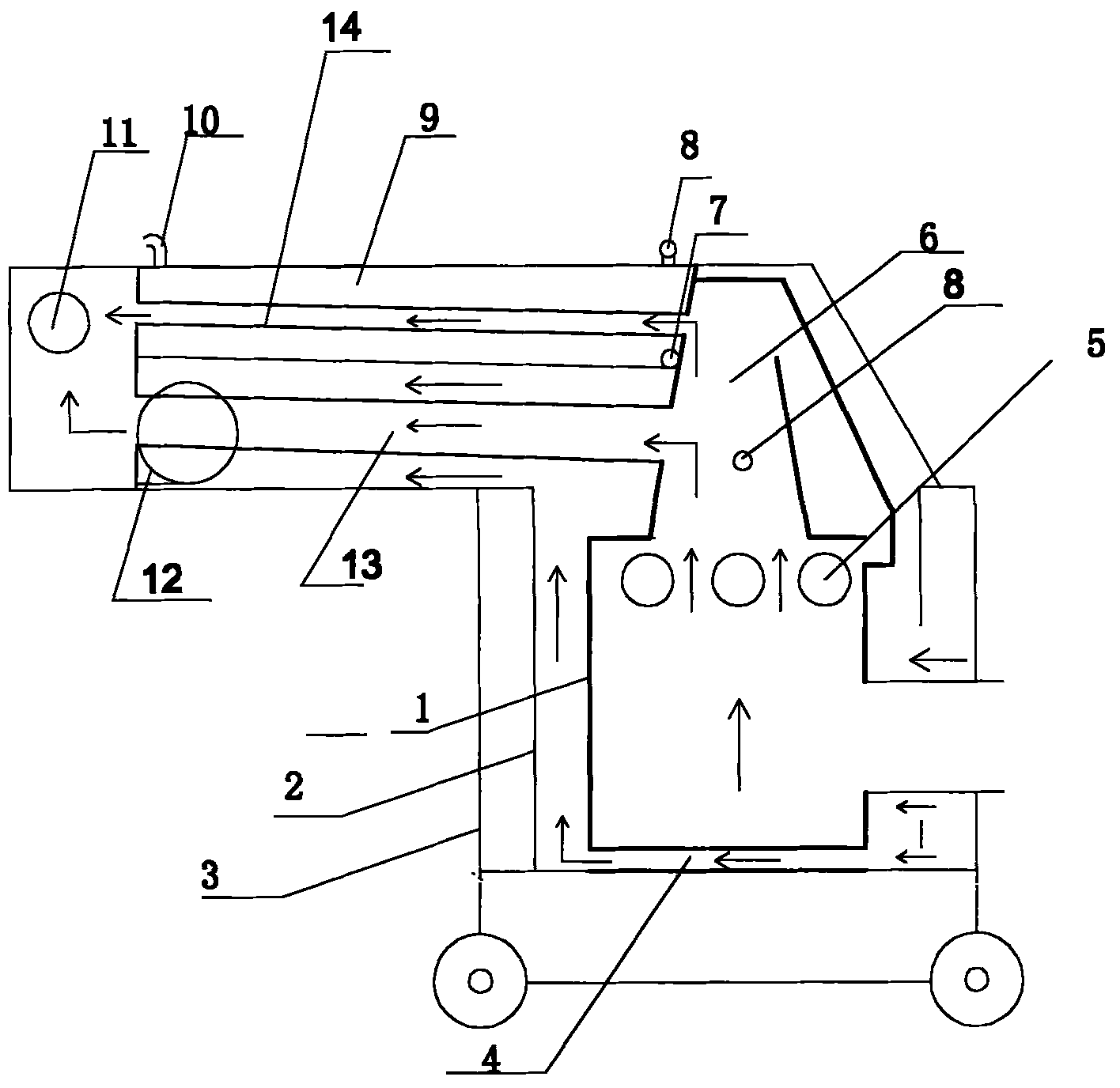
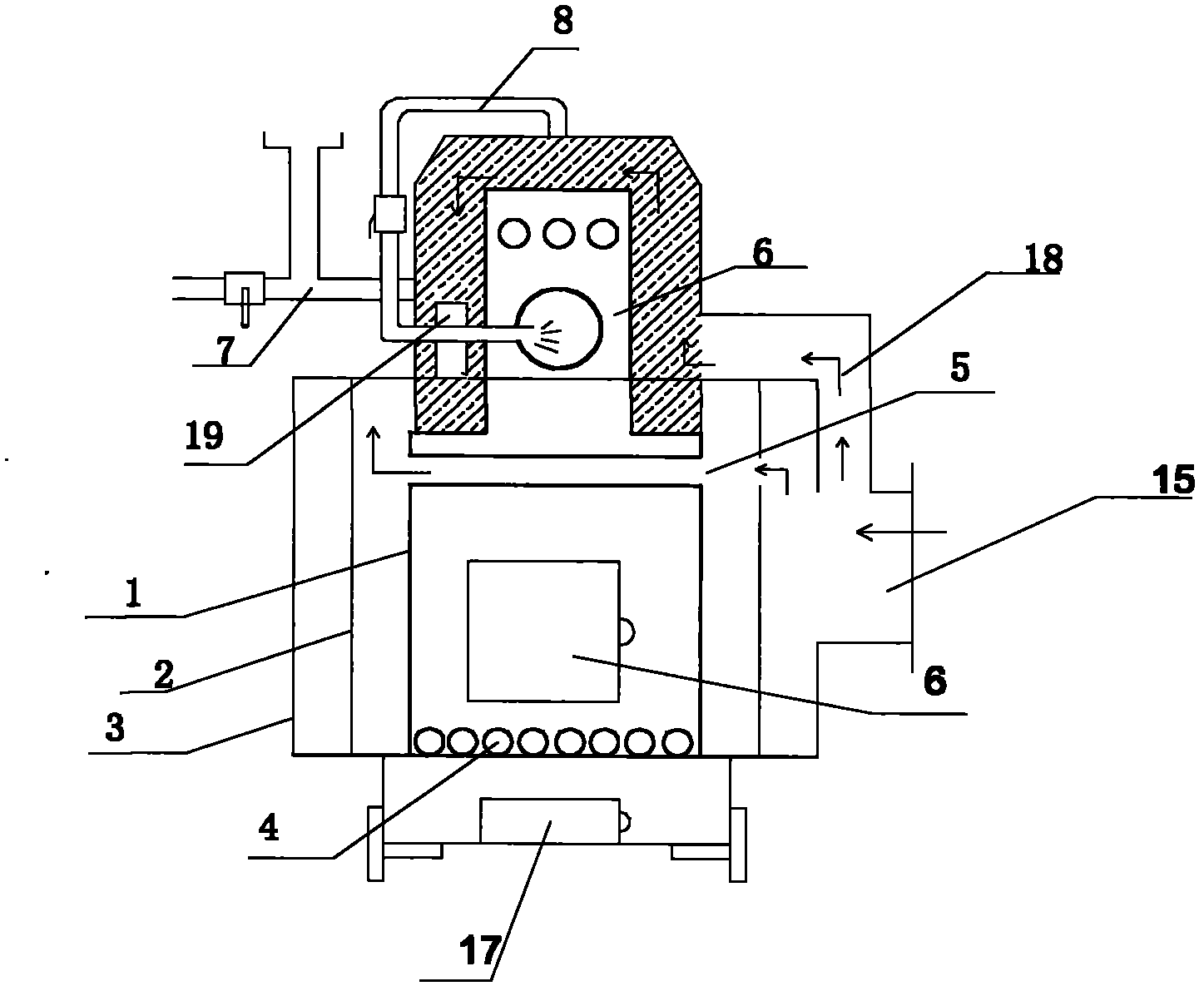
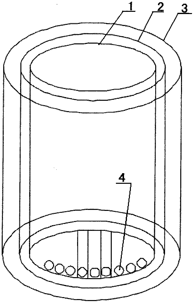
[0026] The structural principle and working principle of the present invention will be further described in detail below in conjunction with the accompanying drawings.

[0027] see figure 1 , 2 , 3, a kind of humidification warm air stove, comprises a furnace inner liner 1, the inner liner 1 is provided with the middle liner liner 2, the middle liner liner 2 is provided with the outer liner liner 3, and the lower part of the liner liner 1 is provided with ventilation Malleable steel grate 4, the upper part is provided with malleable steel heat dissipation pipe 5, and a secondary combustion chamber 6 is provided above the inner tank 1, and a combustion-supporting steam nozzle 8 is provided in the secondary combustion chamber 6, and a water tank is provided on the left side of the secondary combustion chamber 6 9 and the hot air outlet 12, the water tank 9 is provided with a water inlet 7, the auxiliary humidification port 10 inside the house, the water tank 9 is provided with ...


PUM


Abstract

Disclosed is a humidifying air heating furnace. An intermediate-layer sleeve container is arranged on the outside of an inner container, an outer-layer sleeve container is disposed on the outside of the intermediate-layer sleeve container, ventilating malleable cast iron fire bars are disposed on the lower portion of the inner container, malleable cast iron radiating pipes are arranged on the upper portion of the inner container, a secondary combustion chamber is further disposed above the inner container, a water tank and a hot air outlet are disposed on the left side of the secondary combustion chamber, a water adding opening and an indoor auxiliary humidifying opening are disposed on the outside of the water tank, a water tank heating pipe is arranged in the water tank, a hot air heating pipe is arranged inside the hot air outlet, a smoke outlet is disposed on the left side of the water tank, a snail type air blower connecting opening is arranged on the outer-layer sleeve container, and a secondary combustion chamber radiating air inlet channel is arranged above the air blower connecting opening. Air is induced by an induced draft fan to realize combustion supporting, after the temperature of the furnace exceeds 50 DEG C, an air blower delivers cold air to an air channel between the outer-layer sleeve container and the intermediate-layer sleeve container, the cold air is respectively delivered to the surface of the inner container, the ventilating fire bars and the malleable cast iron radiating pipes, and hot air is delivered from a hot air zone to a cultivation room via the air outlet. The humidifying air heating furnace has the advantages that heat exchange efficiency is high, temperature rise is fast, noise is low, smoke leakage is avoided, heat-insulation and energy-saving effects are good, and the humidifying air heating furnace is simple in operation and convenient in maintenance.

Description

technical field [0001] The invention belongs to the technical field of stoves, and in particular relates to a humidifying heater. Background technique [0002] The hearth of the existing humidification heater has fireproof materials such as refractory bricks, the heat transfer and heat exchange speed is very slow, and the energy of burning coal cannot be transferred out in time; the furnace bar is solid cast iron, which cannot conduct heat transfer and is easy to burn out ; Without a secondary combustion chamber, the incompletely burned carbon foam, carbon monoxide, hydrogen sulfide, etc. cannot be fully burned and utilized, and the pollution caused is serious; the hot air cannot be humidified, so that the problem of drying in the chicken house cannot be solved. Contents of the invention [0003] In order to overcome the deficiencies of the above-mentioned prior art, the object of the present invention is to provide a humidifying heater with high heat exchange frequency, f...

Claims


Application Information

Patent Timeline
Patent Type & Authority Applications(China)
IPC IPC(8): F24H3/02F23L7/00F24F6/12A01K31/20
Inventor 吴跃富
Owner 潍坊康富养殖设备有限公司
Why Eureka
Try Eureka