Refrigerant compressor

A technology of compressors and refrigerants, applied in compressors, refrigerators, refrigeration components, etc., can solve the problems of large parts space, high cost, wear, etc., and achieve the effects of space requirements and cost reduction, sound reduction, and strong support

Active Publication Date: 2012-07-11
SECOP GMBH
View PDF7 Cites 6 Cited by
  • Summary
  • Abstract
  • Description
  • Claims
  • Application Information

AI Technical Summary

Problems solved by technology

[0006] This increased load leads to wear in the bearing sleeves and especially in the pin bearings, necessitating overdimensioning of the bearing sleeves or the compr...

Method used


Image

  • Refrigerant compressor
  • Refrigerant compressor
  • Refrigerant compressor

Examples


Embodiment Construction

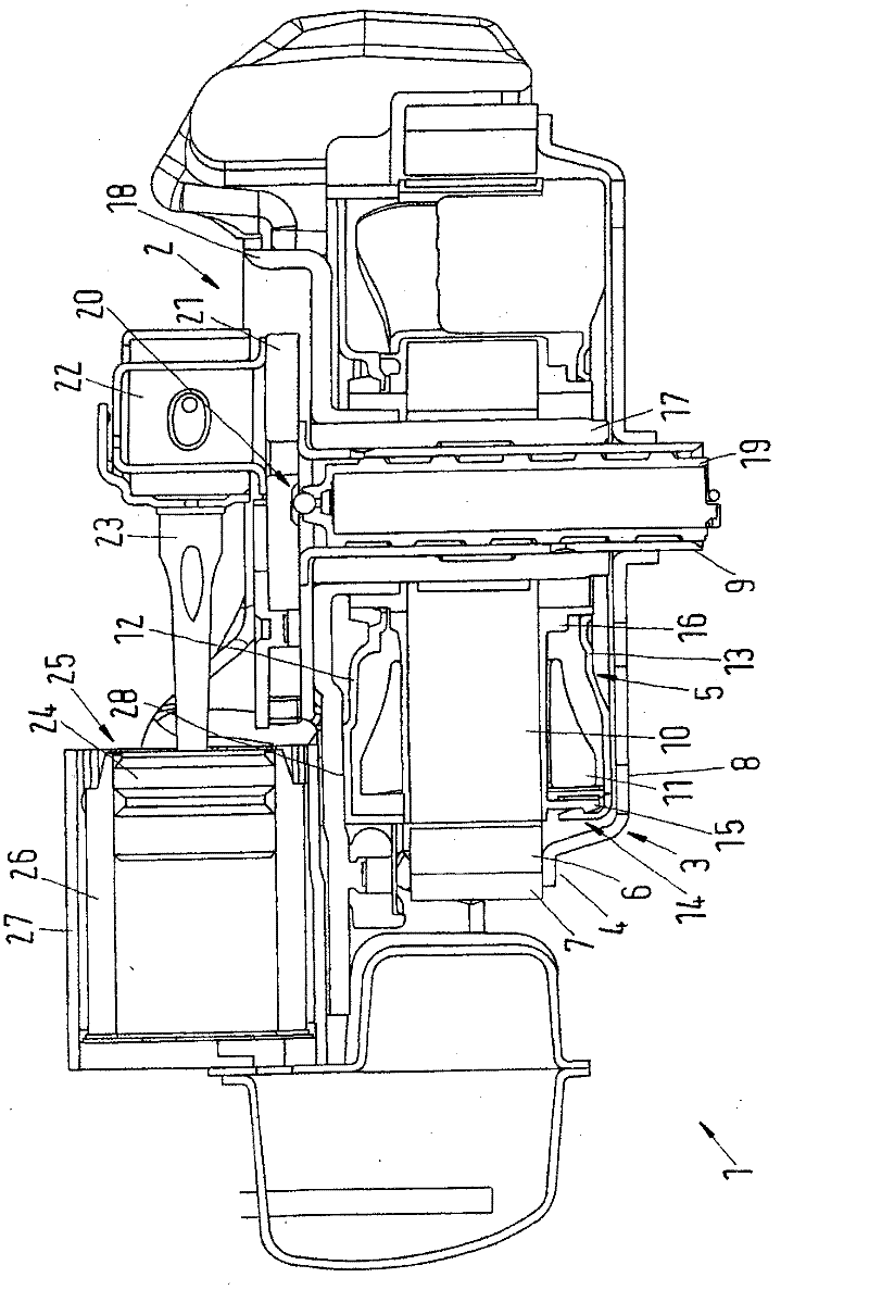
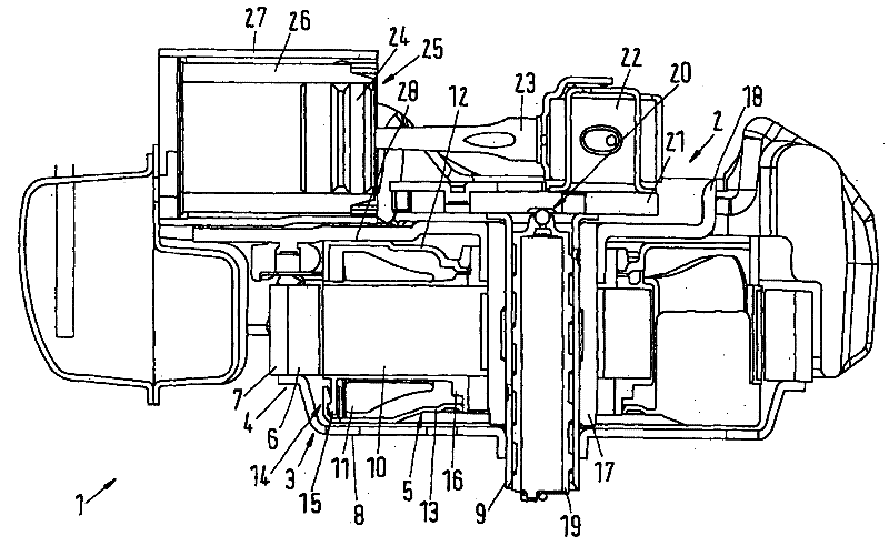
[0025] figure 1 is a schematic sectional view of the refrigerant compressor 1 . The refrigerant compressor 1 includes a compressor assembly 2 and an electric motor 3 , the electric motor 3 is an external rotor type electric motor, and the electric motor has an external rotor 4 and an internal stator 5 . The rotor 4 comprises permanent magnets 6 surrounded radially by short rings 7 . The rotor 4 is connected non-rotatably to a shaft 9 via a plate-shaped base 8 . The lower end of the shaft 9 is immersed in an oil pool not shown.

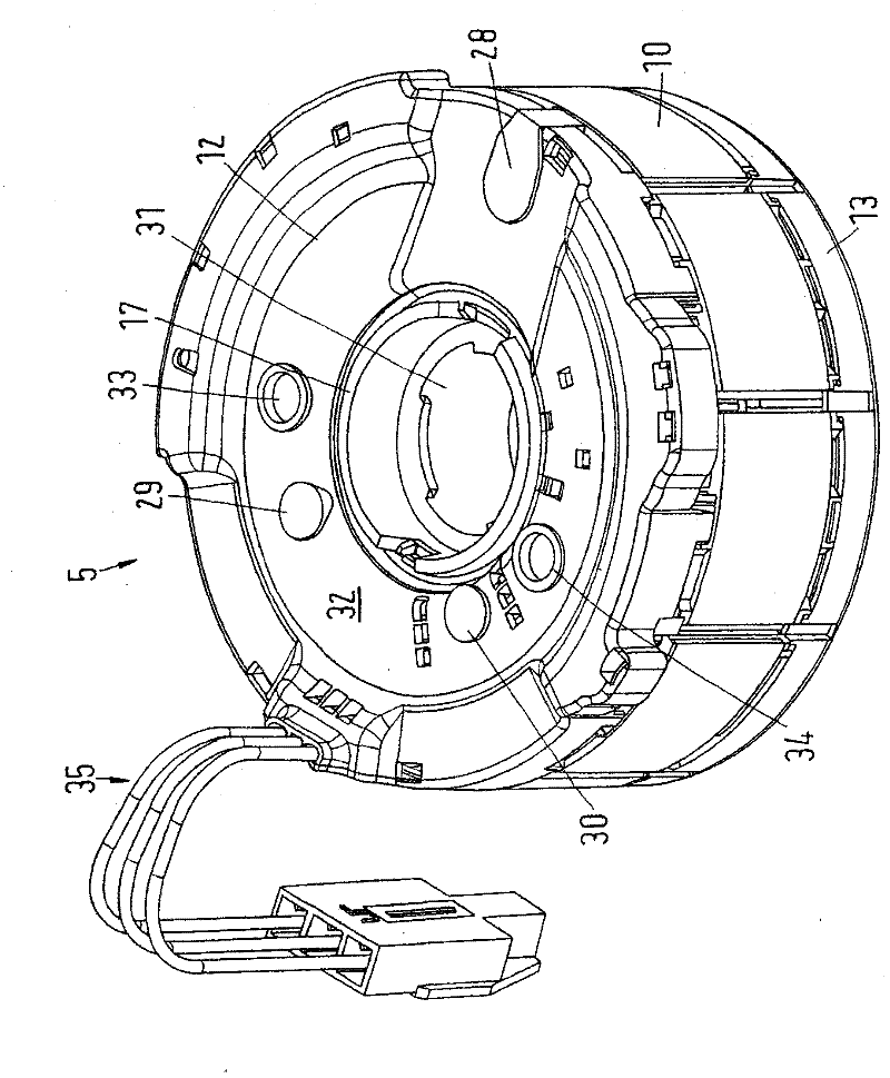
[0026] An annular air gap is formed between the rotor 4 and the stator 5 . The stator 5 comprises a stator lamination 10 and a winding 11 . Furthermore, the stator 5 includes an upper cover plate 12 and a lower cover plate 13 . The cover plates 12 , 13 include radially inwardly directed projections 14 which engage with correspondingly formed parts 15 of the protruding housing 16 of the stator lamination 10 .

[0027] The shaft 9 is supported radi...


PUM


Abstract

The present invention relates to a totally enclosed refrigerant compressor with a compressor assembly (20 and a motor (3), wherein the motor (3) comprises a stator (5) and an external rotor (4), the rotor (4) is connected with a shaft (9) radially supported in the central opening (31) inside the stator (5), the shaft (9) comprises a decentered crank pin (22). In order to prevent the bending load of a bearing sleeve (17) of a radially bearing, the compressor assembly (2) is supported through at least one supporting point (28) on the stator (5).

Description

technical field [0001] The invention relates to a hermetically sealed refrigerant compressor with a compressor assembly and an electric motor, the electric motor includes a stator and a rotor, wherein the rotor is of the outer rotor type, the bearing sleeve of the shaft is arranged in the central opening of the stator, and the shaft cannot be Rotationally connected to the stator, and the shaft is connected to the crank pin at the end facing the compressor assembly. Background technique [0002] In such refrigerant compressors, an eccentric crank pin is used for the purpose of driving a piston-cylinder unit provided in a cylinder assembly. [0003] Refrigerant compressors are used, for example, in refrigeration appliances like freezers, refrigerators and the like. In order to keep the required component space as small as possible, the component height of the refrigerant compressor should be kept as small as possible. Therefore, the component height of the motor needs to be ...

Claims


Application Information

Patent Timeline
IPC IPC(8): F25B31/02
CPCF04B35/04F25B31/023F04B39/122F04B39/127
Inventor M・诺曼森F・H・艾弗森
Owner SECOP GMBH
Why Eureka
Try Eureka